
Integral quenched steel corner back gouging test piece and high-speed milling process method thereof

A high-speed milling and hardening steel technology, applied in milling machine equipment, manufacturing tools, metal processing and other directions, can solve the problem of uneven surface morphology of corner cleaning and root processing, and achieve the effect of meeting the needs of efficient processing

Active Publication Date: 2015-09-16
HARBIN UNIV OF SCI & TECH
View PDF7 Cites 5 Cited by
  • Summary
  • Abstract
  • Description
  • Claims
  • Application Information

AI Technical Summary

Problems solved by technology

[0005] The invention provides an integral hardened steel corner rooting test piece and its high-speed milling process, which solves the problem of uneven surface morphology in high-speed milling mold corner rooting processing

Method used


Image

  • Integral quenched steel corner back gouging test piece and high-speed milling process method thereof
  • Integral quenched steel corner back gouging test piece and high-speed milling process method thereof
  • Integral quenched steel corner back gouging test piece and high-speed milling process method thereof

Examples


Embodiment Construction

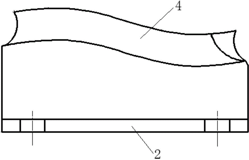
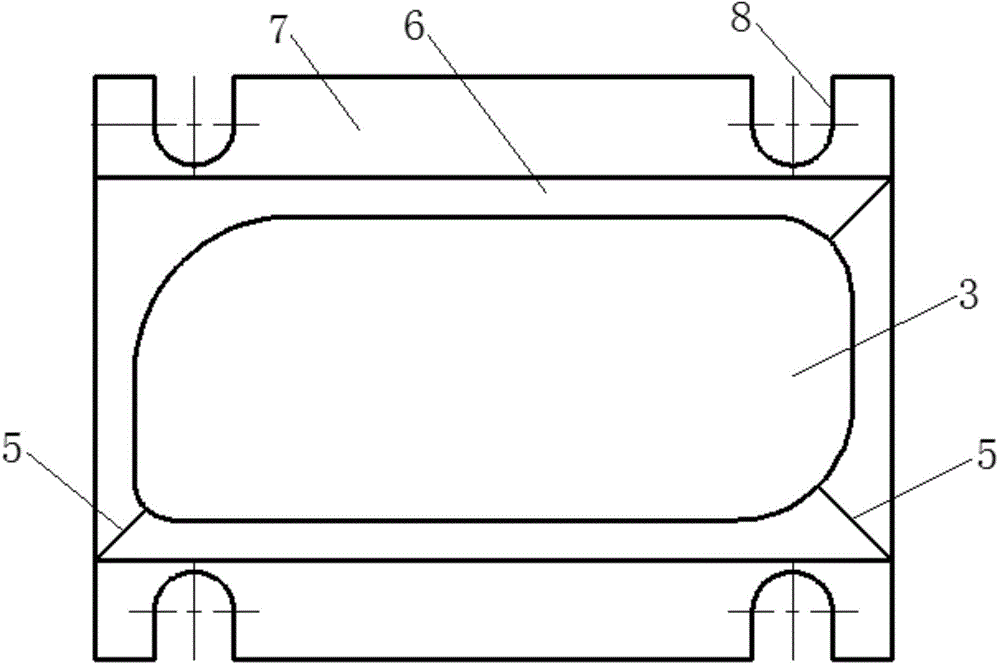
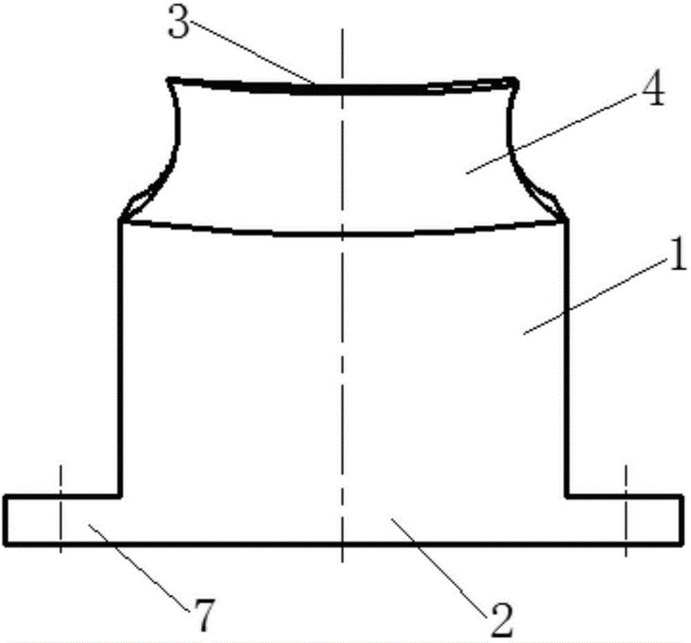
[0034] refer to Figure 1 to Figure 3, the integral hardened steel corner cleaning test piece includes a milling processing area 1 and a base 2 at the bottom thereof, the top surface of the milling processing area 1 is a top concave surface 3 with a curvature radius of 200mm along the width direction, so The top concave surface 3 is composed of 5 sections distributed along the length direction and have different curvature radii and are sequentially connected by smooth transition. The four corners of the top concave surface 3 are arc corners 5 with different radii. On the side elevation, there is a side concave curved surface 4 that is sunken toward its center. On the side elevation of the milling processing area 1, a peripheral convex platform 6 is formed below the side concave curved surface 4. The surface of the peripheral convex platform 6 is parallel to the top surface concave curved surface 3. The upper edge of the side concave curved surface 4 intersects the edge of the ...


PUM


Abstract

The invention relates to an integral quenched steel back gouging test piece and a high-speed milling process method thereof. The technical key points are as follows: the test piece comprises a milling processing region and a base at the bottom, wherein the top surface of the milling processing region is a top concave curve surface which is bent downwards along the width direction, the top concave curve surface is formed by smooth transition connection of five sections of curve surfaces which are distributed along the length direction and have different curvature radiuses, the four corners of the top concave curve surface are circular arc corners which have different radiuses, the side vertical surface of the milling processing region is provided with one section of side concave curve surface which sinks towards the center, a circumferential lug boss which is positioned below the side concave curve surface is formed on the side vertical surface of the milling processing region, and the surface of the circumferential lug boss is parallel to the top concave curve surface; two sides of the base, in the width direction of the milling processing region, extend outwards to form a lug boss. According to the process scheme, the method comprises the steps of step one, selecting the processing region; step two, designing the cutting path of a cutter; and step three, processing the surface feature when the high-speed quenched steel back gouging is tested.

Description

Technical field: [0001] The invention relates to a high-speed milling hardened steel mold corner rooting test piece and a process design method thereof, in particular to an integral hardened steel corner rooting test piece and a high-speed milling process method thereof. Background technique: [0002] When using a ball end milling cutter to cut the corner of the hardened steel mold insert, the complex curvature of the machined surface makes the cutting force and the vibration of the milling cutter in an unstable state, resulting in the deterioration of the machined surface morphology and serious wear of the milling cutter. Reduced service life and cutting efficiency. Affected by the frequent changes of the curvature of the hardened steel workpiece and the machining inclination angle and the reduction of the feed rate at the corner of the milling cutter, the cutting force and the vibration of the milling cutter are in an unstable state; at the same time, it is found that the ...

Claims


Application Information

Patent Timeline
IPC IPC(8): B23C3/00B23Q15/00
CPCB23C3/00B23Q17/00B23Q17/20
Inventor 姜彬张帅
Owner HARBIN UNIV OF SCI & TECH
Learn More