Lifting tool and lifting method applying tool
A hoisting and tooling technology, which is applied in the field of machining equipment, can solve the problems that a single crane cannot meet the installation requirements, aggravate the difficulty of the rack, and low lifting height, so as to achieve stability, reduce lifting requirements, and reduce The effect of rolling heavy objects
- Summary
- Abstract
- Description
- Claims
- Application Information
AI Technical Summary
Problems solved by technology
Method used
Image
Examples
Embodiment 1
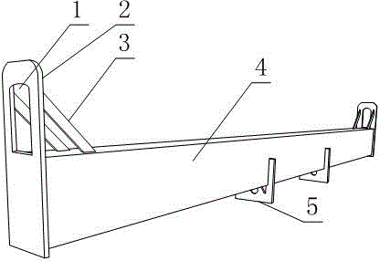
[0027] Such as Figure 1 to Figure 3 , a kind of hoisting tooling, comprising beam 4, lifting lug 2 and shackle plate 5, described lifting lug 2 is two, and two lifting lugs 2 are respectively fixed on the different end of beam 4, and described lifting lug 2 is provided with The plate structure of the hook hole 1, and the lower end of the lifting ear 2 is fixed on the beam 4, and the hook hole 1 is located at the upper end of the lifting ear 2;
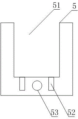
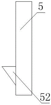
[0028] The shackle plate 5 is at least two, and the shackle plate 5 is a plate structure provided with an engagement groove 51 and a shackle hole 53. The bottom surface and the side surface of the engagement groove 51 are welded to the bottom surface and the side surface of the beam 4 respectively, The buckle holes 53 are located below the engaging grooves 51 , and the shackle plates 5 are respectively fixed at different positions along the length direction of the beam 4 .
[0029] In this embodiment, the hook holes 1 respectively pr...
Embodiment 2
[0031] This embodiment further limits this scheme on the basis of embodiment 1: as Figure 1 to Figure 3, as a structural form in which the crossbeam 4 has a good flexural modulus under the same weight or material consumption, the crossbeam 4 is in the shape of a hollow rectangular beam. At the same time, the above structure facilitates the manufacture of crossbeams 4 with suitable strength or volume through steel plates, channel steels, angle steels and other materials according to actual requirements after mechanical calculations.
[0032] Since the bending moment on the crossbeam 4 in the working process of the present invention will inevitably cause the center of the crossbeam 4 to be concavely bent to both ends, like this, the interaction force between the driving hook and the lifting lug 2 will be reduced under the ideal operating state. , The interaction force between the shackle plate 5 and connecting parts such as slings, wire ropes or shackles does not necessaril...
Embodiment 3
[0036] This embodiment provides a method of adopting the structure provided by any one of the schemes in Embodiment 1 or Embodiment 2 to realize the transfer of the frame of the grader from the unloading point to the installation point in the workshop: a hoisting method, The method adopts any one of the lifting fixtures described above to realize the installation and lifting of the tempering machine frame in the factory building, including the following steps carried out in sequence:
[0037] 1) Transfer the skin pass machine frame to the factory building through the transportation equipment;
[0038] 2) Brake the two cranes to the top of the tempering machine frame, and at the same time fasten the hooks of the two cranes to the different hook holes 1 of the hoisting tooling, and each shackle hole 53 of the shackle plate 5 There is a shackle in each;
[0039] 3) According to the shackle plate 5, determine the lifting point on the frame of the grader, or set the position o...
PUM
| Property | Measurement | Unit |
|---|---|---|
| Thickness | aaaaa | aaaaa |
| Length | aaaaa | aaaaa |
| Height | aaaaa | aaaaa |
Abstract
Description
Claims
Application Information
 - R&D Engineer
- R&D Manager
- IP Professional
- Industry Leading Data Capabilities
- Powerful AI technology
- Patent DNA Extraction
Browse by: Latest US Patents, China's latest patents, Technical Efficacy Thesaurus, Application Domain, Technology Topic, Popular Technical Reports.
© 2024 PatSnap. All rights reserved.Legal|Privacy policy|Modern Slavery Act Transparency Statement|Sitemap|About US| Contact US: help@patsnap.com


