
Magnetic filtration and separation device

A separation device and magnetic filtration technology, applied in the direction of filtration separation, separation methods, chemical instruments and methods, etc., can solve the problems of slow response to magnetic field induction, large magnetic energy consumption of electromagnetic coils, uneven distribution of permanent magnet magnetic field, etc., to achieve Enhanced adsorption separation and filterability, uniform magnetic force distribution, and the effect of innovative design goals

Active Publication Date: 2015-09-09
SHANGHAI FINETAC PRECISION TECH CO LTD
View PDF3 Cites 6 Cited by
  • Summary
  • Abstract
  • Description
  • Claims
  • Application Information

AI Technical Summary

Problems solved by technology

[0002] Magnetic filters are mainly used in petroleum, chemical industry, metallurgy, medicine, machinery, automobile and other fields to remove a large amount of iron filings, iron powder and other ferromagnetic impurities contained in various liquids, slurries and gases, and can be used for precious metal catalysts Recovery and clarification of weak magnetic medium, etc. With the rapid development of petrochemical industry, including emerging coal chemical industry, metallurgy, automobile industry and the strengthening of environmental protection, especially for the hydrogenation reaction of polyaromatic hydrocarbons in coal chemical industry; high catalytic activity Raney nickel catalyst The requirement for recycling is becoming more and more urgent. The permanent magnet separation made of traditional rare earth materials is limited by the inherent magnetic field strength and cannot be adjusted, the uniformity of the magnetic field distribution is poor, and the efficiency of filtration and separation is not high. In terms of separation effect and application range There are many limitations in the field and field. At present, the magnetic filter mainly uses permanent magnets as the filter core to remove ferromagnetic particles in the medium. However, due to the uneven distribution of the magnetic field of the permanent magnets, the filtration efficiency is not high, and the magnetic energy consumed by the electromagnetic coil It is easy to burn out when the temperature is high, the maintenance and replacement process is complicated and troublesome, and it is difficult to meet the application occasions with certain precision requirements; in addition, the magnetic filter mainly uses water as the backwash medium in the process of backwashing, and the backwashing efficiency is low. consumes a lot
[0003] Most of the electromagnetic separation devices or systems at home and abroad are used in the magnetic separation of lean iron ore. Compared with such products, the innovative structural design of the product of this project makes the uniformity of the magnetic field better and the gradient distribution under the same magnetic field strength. More reasonable; the temperature and corrosion resistance of the filter element is more prominent; the specially designed structure can use the gas-liquid backwashing process to realize the efficient cleaning of the filter residue; the automatic temperature control device is used to control the temperature rise of the electromagnetic coil. Under the changes of temperature, pressure, vibration, liquid flow and speed, the magnetic filter responds slowly and cannot keep up with the requirements of actual working conditions

Method used


Image

  • Magnetic filtration and separation device
  • Magnetic filtration and separation device
  • Magnetic filtration and separation device

Examples


Embodiment Construction

[0023] specific implementation

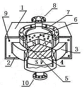
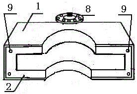
[0024] A magnetic filtering and separating device, composed of a magnetic field regulator 1, a magnetic resistance sheet 2, a magnetic quantum generator 3, a magnetic rotating net 6, a pressure magnetic ring 7, a liquid outlet 8, a positioning pin hole 9, and a liquid inlet 10 , the magnetic quantum generator 3 is inserted in the concave box nest of the magnetic field adjuster 1, the magnetic resistance sheet 2 is fixedly embedded in the four corner positioning holes of the semicircle concave section of the magnetic field adjuster 1 according to the positioning pin hole 9, and the magnetic rotation net 6 It is fixed on the magnetic drum 5 by the pressure magnetic ring 7.

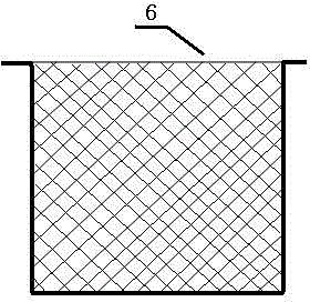
[0025] A liquid outlet 8 and a liquid inlet 10 are installed on the top and bottom of the magnetic drum 5, which are fixed by a magnetic pressure ring 7 with screws. 6. Fold the edge of the circumference of 60mm outwards, (see attached figure 2 , 3 ).

[0026] The material ...


PUM


Abstract

The invention relates to a magnetic filtration and separation device, which consists of a magnetic field regulator, a magnetic resistance chip, a magnetic quantum generator, a gyromagnetic net, a piezomagnetic ring, a liquid outlet, positioning pin holes, and a liquid inlet. The magnetic quantum generator is wedged into a concave box nest of the magnetic field regulator, the magnetic resistance chip is fixedly embedded to four corner point positioning holes of the magnetic field regulator's semicircular concave section through the positioning pin holes, the gyromagnetic net is fixed on a magnetic rotating drum through the piezomagnetic ring, and the upper part and the lower part of the magnetic rotating drum are respectively provided with the liquid outlet and the liquid inlet that are fixed by the piezomagnetic ring with screw. By means of the electromagnetic filter technology, the magnetic field regulator realizes energy-saving innovation of electromagnetic filter, the magnetic field with internal gradient can realize automatic adjustment of lifting according to needs, the magnetic force distribution is even, the filter element adsorbability is strong, and the filtration efficiency is high. The magnetic filtration and separation device provided by the invention has increasingly important significance and market opportunity for recovery of high catalytic activity raney nickel catalyst in poly-aromatic hydrocarbon hydrogenation reaction.

Description

technical field [0001] The invention relates to magnetic quantum collection and distribution in magnetic field strength, and is an innovation in the core technology device of electromagnetic separation, specifically a magnetic filtration and separation device, a device that can synchronize filtration and separation, and belongs to the field of magnetic filtration. Background technique [0002] Magnetic filters are mainly used in petroleum, chemical industry, metallurgy, medicine, machinery, automobile and other fields to remove a large amount of iron filings, iron powder and other ferromagnetic impurities contained in various liquids, slurries and gases, and can be used for precious metal catalysts Recovery and clarification of weak magnetic medium, etc. With the rapid development of petrochemical industry, including emerging coal chemical industry, metallurgy, automobile industry and the strengthening of environmental protection, especially for the hydrogenation reaction of ...

Claims


Application Information

Patent Timeline
Patent Type & Authority Applications(China)
IPC IPC(8): B01D35/06
Inventor 何向阳何晟何秦雷鉴源
Owner SHANGHAI FINETAC PRECISION TECH CO LTD
Learn More