
A test structure and its manufacturing method

A technology for testing structures and manufacturing methods, applied in semiconductor/solid-state device manufacturing, electrical components, electric solid-state devices, etc., can solve problems such as easy damage and unfavorable failure analysis, so as to avoid device damage, improve failure analysis efficiency, and reduce cost effect

Active Publication Date: 2017-12-19
SEMICON MFG INT (SHANGHAI) CORP
View PDF4 Cites 0 Cited by
  • Summary
  • Abstract
  • Description
  • Claims
  • Application Information

AI Technical Summary

Problems solved by technology

[0009] In view of the shortcomings of the prior art described above, the purpose of the present invention is to provide a test structure and its manufacturing method, which is used to solve the problem that the test structure in the prior art is easily damaged in the process of repeated wiring, which is not conducive to failure analysis The problem

Method used


Image

  • A test structure and its manufacturing method
  • A test structure and its manufacturing method
  • A test structure and its manufacturing method

Examples


Embodiment 1

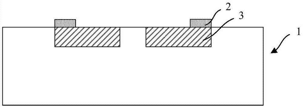
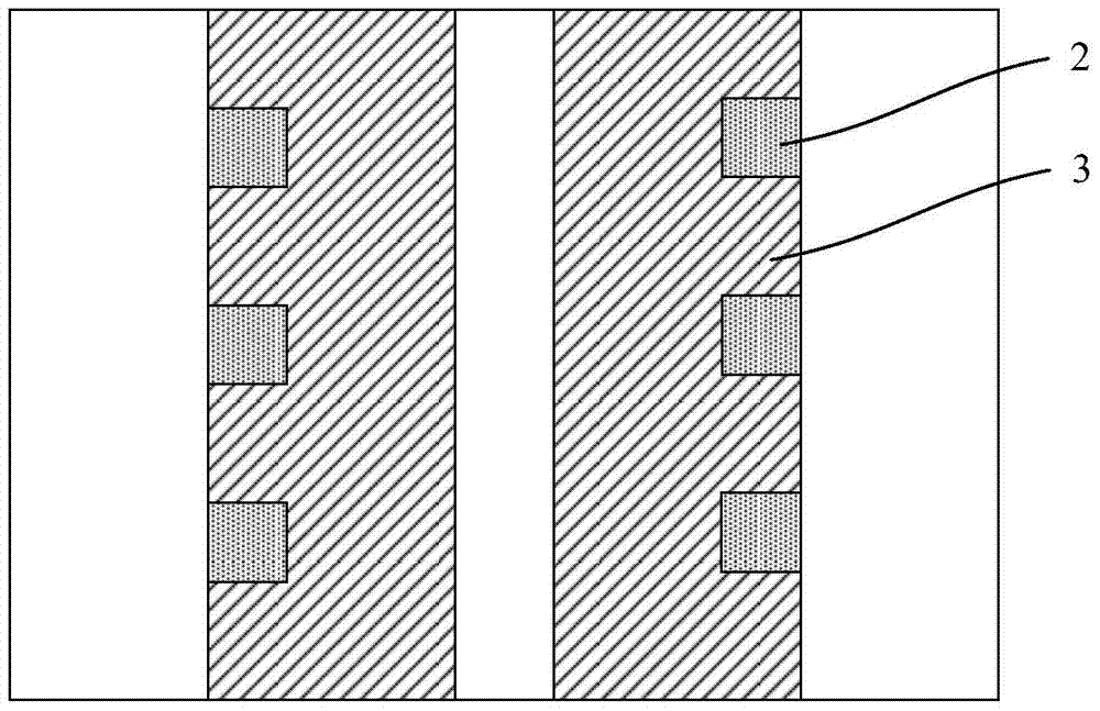
[0046] see Figure 2 to Figure 5 , is shown as an embodiment of the manufacturing method of the test structure of the present invention.

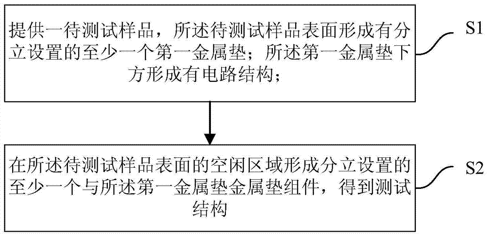
[0047] See first figure 2 , performing step S1: providing a sample to be tested 1, the surface of the sample to be tested 1 is formed with at least one discrete first metal pad 2; a circuit structure 3 is formed under the first metal pad 2.

[0048] Specifically, the sample 1 to be tested can be a device structure that has passed a reliability test. After the reliability test, failure analysis needs to be performed, and the chip can be unpacked to take out the device structure. During the removal process, the device structure has been bonded before. The bonded wires are pulled off, and because electrical signals need to be connected in failure analysis, it is necessary to re-bond the wires (also called wire bonding).

[0049] Specifically, the first metal pad 2 may be a metal pad such as an aluminum pad or a copper pad. Due to the minia...

Embodiment 2

[0058] see Figure 6 to Figure 7 , showing another embodiment of the manufacturing method of the test structure of the present invention.

[0059] See first Figure 6 , performing steps S1 and S2: providing a sample to be tested, the surface of the sample to be tested is formed with at least one discrete first metal pad 2; a circuit structure 3 is formed under the first metal pad 2; The free area on the surface of the sample to be tested forms at least one discrete metal pad assembly connected to the first metal pad 2 to obtain a test structure.

[0060] Specifically, the metal pad assembly is composed of a pair of second metal pads 4, the pair of second metal pads are connected to each other by a metal wire 5, and one of the second metal pads is connected to the first metal pad. In this embodiment, the sample to be tested is described as an example including two columns of circuit structures 3 and corresponding two columns of first metal pads 2 . The metal pad assembly is ...


PUM


Abstract

The present invention provides a test structure and a manufacturing method thereof. The method includes the following steps: 1) providing a sample to be tested, wherein at least one first metal pad is discretely arranged on the surface of the sample to be tested; the first metal pad A circuit structure is formed below; 2) At least one metal pad component connected to the first metal pad is formed discretely on the free area of ​​the surface of the sample to be tested to obtain a test structure. The present invention forms an additional metal pad assembly on the basis of the original metal pad in the test sample, wherein the metal pad assembly is formed in the free area of ​​the test sample and will not affect the test sample; the metal pad assembly can be used for wire bonding in the failure analysis stage Access to electrical signals avoids device damage caused by repeated bonding or cracks of the device under the first metal pad, which is conducive to improving the efficiency of failure analysis; and both gold wire bonding and aluminum wire bonding can be used to reduce costs .

Description

technical field [0001] The invention belongs to the field of semiconductor manufacturing, and relates to a test structure and a manufacturing method thereof. Background technique [0002] Generally speaking, the failure of integrated circuits is inevitable in the process of development, production and use. With the continuous improvement of people's requirements for product quality and reliability, failure analysis is becoming more and more important. Through chip failure analysis, it can help integrate Circuit designers find design flaws, mismatches in process parameters, or improper design and operation. [0003] The significance of failure analysis is mainly manifested in the following aspects: 1) Failure analysis is a necessary means to determine the failure mechanism of chips; 2) Failure analysis provides necessary information for effective fault diagnosis; 3) Failure analysis provides design engineers with continuous improvement or Repair the design of the chip to mak...

Claims


Application Information

Patent Timeline
Patent Type & Authority Patents(China)
IPC IPC(8): H01L21/02H01L23/544
Inventor 张卿彦
Owner SEMICON MFG INT (SHANGHAI) CORP
Learn More