
Distributing cable partial discharge test method based on oscillatory wave test

A partial discharge and power distribution cable technology, applied in the direction of testing dielectric strength, etc., can solve problems such as failure to detect discharge, rapid breakdown of insulation, cable damage, etc., to eliminate discharge interference, avoid cluttered discharge points, and increase testing. range effect

Inactive Publication Date: 2015-07-29
STATE GRID CORP OF CHINA +1
View PDF7 Cites 16 Cited by
  • Summary
  • Abstract
  • Description
  • Claims
  • Application Information

AI Technical Summary

Problems solved by technology

Usually, these methods can only judge the voltage condition of the cable on the one hand, but cannot judge the defect point of the cable insulation, let alone discover and locate the hidden danger of partial discharge. On the other hand, this kind of test is a destructive test. The insulation has a certain destructive effect, especially after the DC high voltage test, the molecular arrangement of the polarized state is still maintained inside the cross-linked polyethylene insulation, and it is not easy to return to the state before the pressure is applied, which leads to the insulation of the cables that pass the test after power transmission. Accidents that are quickly broken down happen from time to time

Method used


Image

  • Distributing cable partial discharge test method based on oscillatory wave test
  • Distributing cable partial discharge test method based on oscillatory wave test
  • Distributing cable partial discharge test method based on oscillatory wave test

Examples


Embodiment Construction

[0039] The method for testing partial discharge of power distribution cables based on oscillating wave testing provided by the present invention will be described in detail below with reference to the accompanying drawings and specific embodiments.

[0040] The method for testing partial discharge of power distribution cables based on oscillating wave testing provided by the present invention includes the following steps performed in sequence:

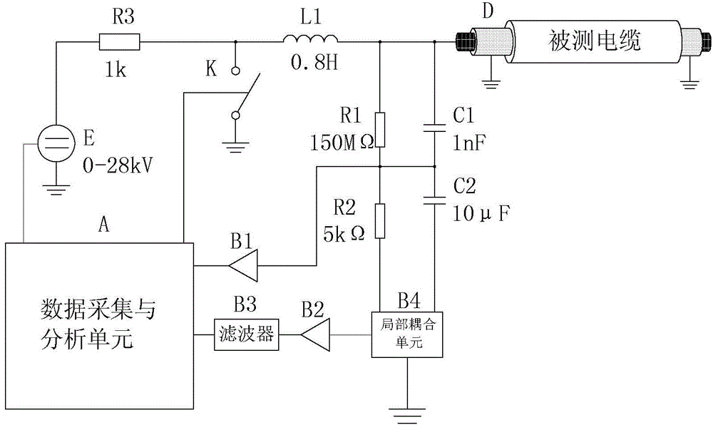
[0041] Step 1) Establish a test system: establish a cable partial discharge test and positioning system based on oscillatory wave testing;

[0042] Step 2) Test: use the above-mentioned cable partial discharge testing and positioning system to charge the cable by pressing the end of the cable under test to a preset value, and pass the inductance of the cable partial discharge testing and positioning system to the cable under test. The capacitor resonates and a damped oscillating voltage is generated at the end of the cable under test; ...


PUM


Abstract

Disclosed is a distributing cable partial discharge test method based on oscillatory wave test. The method includes that a cable partial discharge testing and locating system based on oscillatory wave test is established; by means of the testing system, a cable is charged through a method of voltage increasing to a preset value at a tested cable end, and damped oscillation voltage is generated at the tested cable end through resonance oscillation that occurs by an inductor and a tested cable capacitor in the system; when partial discharge occurs at a position of the tested cable in a distance from a testing end, pulses can spread in two directions along the cable, and the position where the partial discharge occurs can be determined according to time difference that two pulses such as incident wave and radioactive wave reach the testing end. According to the distributing cable partial discharge test method based on oscillatory wave test, oscillatory wave is applied to partial discharge test of the distributing cable, and voltage increasing is performed on the cable through sine oscillatory wave that is generated by resonance oscillation of fixed inductor and the cable. By means of the distributing cable partial discharge test method based on oscillatory wave test, insulating conditions of the cable can be timely known within short time by the system, and thereby, accidents of the cable can be effectively prevented.

Description

technical field [0001] The invention belongs to the technical field of partial discharge detection, in particular to a partial discharge test method for distribution cables based on oscillating wave testing. Background technique [0002] In the power system, the commonly used cable testing method is to add DC high voltage to the tested cable to check the magnitude of DC leakage current, 0.1Hz ultra-low frequency AC withstand voltage test, etc. Usually, these methods can only judge the condition of the cable withstanding voltage on the one hand, but cannot judge the defect points of the cable insulation, let alone find and locate the hidden danger of partial discharge. On the other hand, this kind of test is a destructive test. The insulation has a certain destructive effect, especially after the DC high voltage test, the molecular arrangement of the XLPE insulation still maintains a polarized state, and it is not easy to restore to the state before the pressure, so that the ...

Claims


Application Information

Patent Timeline
IPC IPC(8): G01R31/12
Inventor 张晓虹马力耿芳范伟张梅侯彩龙
Owner STATE GRID CORP OF CHINA
Learn More