Built-in multiple-disk braking permanent magnet motor

A permanent magnet motor, built-in technology, applied in the direction of controlling mechanical energy, electrical components, electromechanical devices, etc., can solve the problems of large diameter of brake flange, limited application of permanent magnet motor, large space, etc., to reduce manufacturing costs and operation. Cost, reduction in size and weight, effect of simplifying the overall structure

Active Publication Date: 2015-07-22
JIANGXI GONGBU MACHINERY
View PDF6 Cites 3 Cited by
  • Summary
  • Abstract
  • Description
  • Claims
  • Application Information

AI Technical Summary

Problems solved by technology

In order to achieve this braking, the diameter of the brake flange is often large, and the installation of the caliper brake device needs to occupy a large space, especially in the radial direction of the drum, which severely limits The application of permanent magnet motors in cranes and other fields

Method used


Image

  • Built-in multiple-disk braking permanent magnet motor
  • Built-in multiple-disk braking permanent magnet motor
  • Built-in multiple-disk braking permanent magnet motor

Examples


Embodiment Construction

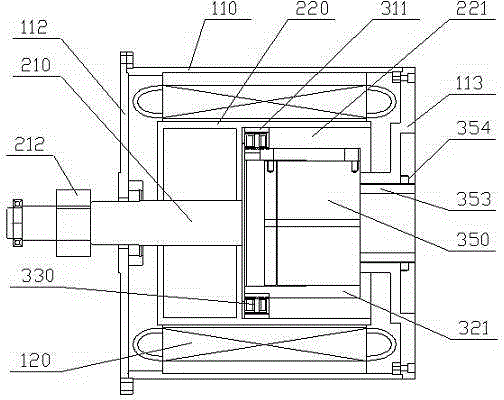
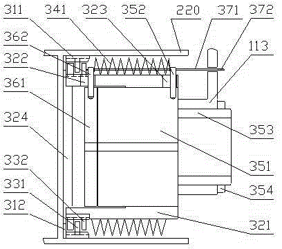
[0009] see Figure 1-3 , The built-in multi-disc brake permanent magnet motor disclosed in the present invention includes a rotor 220, a stator and a built-in brake device, the rotor is located in the stator and is connected to the stator through a bearing for rotation, and the iron core of the stator 120 is installed in the casing 110 of the motor. The casing is provided with a front end cover 112 and a rear end cover 113. The rotating shaft 210 of the rotor faces forward and extends from the shaft hole of the front end cover to form the output of the motor. The shaft is usually equipped with an output gear 212, and the rear part of the rotor is a cylindrical section with an open rear end, which is provided with a cylindrical space 221 capable of accommodating the built-in multi-disc braking device. The moving device includes a rotating cylinder 311, a brake cylinder 321, a brake disc assembly 330, an elastic device and a power device 350. The brake disc 331 and the static b...


PUM


Abstract

The invention relates to a built-in multiple-disk braking permanent magnet motor, a multiple-disk braking device is arranged in the rear part of the rotor of the built-in multiple-disk braking permanent magnet motor, the multiple-disk braking device comprises a rotating drum, braking drum, a brake disc assembly, an elastic force device and a power plant, a dynamic brake disc and a static brake disc in the brake disc assembly are in stagger distribution, the dynamic brake disc is flexibly connected with the rotating drum in the axial direction, the static brake disc and the braking drum move in the axial direction, the elastic force device is positioned on the rear side of the brake disc assembly and provided with a spring / spring assembly that applies forward thrust to the brake disc positioned on the aftermost side, the rotating drum is fixedly installed on the inner wall of the drum-like segment of the rear part of the rotor or directly adopts the drum-like segment of the rear part of the rotor, and the rear end of the basal body of the power plant is fixedly connected with a rear end cover. The multiple-disk braking permanent magnet motor has a braking function, and can remarkably simplify the whole structure and reduce the whole volume, the manufacturing cost and the operating expense when applied to a crane and other equipment.

Description

technical field [0001] The invention relates to a built-in multi-disk brake permanent magnet motor. Background technique [0002] Due to the wide speed range of the existing permanent magnet motor, it is allowed to run at a lower speed. When used in cranes and other equipment, the requirements for the reducer can be significantly reduced, and the reducer can be simplified or even eliminated. The magneto does not have a built-in brake device. When used in cranes and other equipment, an independent brake device needs to be installed separately. The commonly used brake device is a caliper brake device, which is installed on one side of the drum. The caliper grips the brake flange or disc for braking. In order to achieve this braking, the diameter of the brake flange is often large, and the installation of the caliper brake device needs to occupy a large space, especially in the radial direction of the drum, which severely limits The application of permanent magnet motors in c...

Claims


Application Information

Patent Timeline
IPC IPC(8): H02K7/102H02K21/02
Inventor 喻立号喻林
Owner JIANGXI GONGBU MACHINERY
Why Eureka
Try Eureka