Multi-layer parallel stacked frame type spray flue gas waste heat recovery heat exchange device
A flue gas waste heat and heat exchange device technology, applied in direct contact heat exchangers, heat exchanger types, water shower coolers, etc. Thermal effect and other issues, to achieve the effect of reducing the operating cost of the device, facilitating the monitoring of equipment quality, and reducing the amount of flue gas treatment
- Summary
- Abstract
- Description
- Claims
- Application Information
AI Technical Summary
Problems solved by technology
Method used
Image
Examples
Embodiment 1
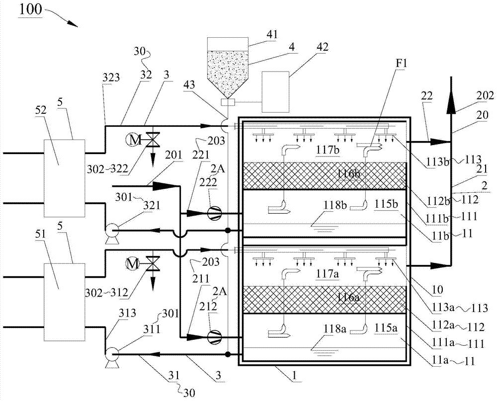
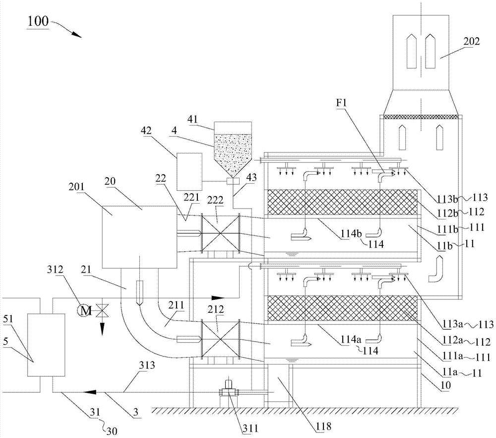
[0076] In the first embodiment, if Figure 1-Figure 6 As shown, the flue gas waste heat recovery heat exchange tower 1 includes the first spray flue gas waste heat recovery heat exchange assembly 11a and the second spray flue gas waste heat recovery heat exchange assembly 11b, and the second spray flue gas waste heat recovery heat exchange assembly 11b. The heat component 11b is located above the heat exchange component 11a for recovery of waste heat from spraying flue gas on the first layer, and the two are supported and connected as a whole by the frame structure 10 of the heat exchange tower.
[0077] In Embodiment 1, the branch flue system 203 of the multi-layer stacked parallel flue gas system 2 includes the first layer branch flue system 21 and the second layer branch flue system 22 to respectively connect the waste heat of the first layer spraying flue gas The recovery heat exchange component 11a and the second layer spray flue gas waste heat recovery heat exchange comp...
Embodiment 2
[0097] In the second embodiment, if Figure 7-Figure 8 As shown, the structure of the multi-layer parallel stacked frame type shower flue gas waste heat recovery heat exchange device 100 in Embodiment 2 is substantially the same as that of the first embodiment. I won't go into details here.
[0098] The difference is that in the second embodiment, as Figure 7 As shown, one end of the alkali addition pipeline system 43 of the alkali addition neutralization system 4 is connected to the alkali addition storage tank 41, and the other end of the alkali addition pipeline system 43 is respectively connected to a plurality of spray flue gas waste heat recovery heat exchange components 11. The accommodating spaces V are connected, that is to say, the alkaline neutralization system 4 directly puts alkaline substances into the accommodating spaces V of the corresponding spray flue gas waste heat recovery heat exchange components 11 to neutralize the spray water.
[0099] In the second...
Embodiment 3
[0106] In the third embodiment, such as Figure 9 As shown, the structure of the multi-layer parallel stacked frame type spray flue gas waste heat recovery heat exchange device 100 in Embodiment 3 is basically the same as the multilayer parallel stacked frame type spray flue gas waste heat recovery heat exchange device 100 in Embodiment 1. I won't go into details here.
[0107] The difference is that in Example 1, as figure 1 As shown, the fan 2A of the multi-layer stacked parallel flue gas system 2 is connected in series to the main inlet flue 201, and the fan 2A is set before the flue gas waste heat recovery heat exchange tower 1, that is, the flue gas conveying fan in Embodiment 1 adopts front drive Way.
[0108] And in embodiment three, if Figure 9 As shown, the multi-layer stacked parallel flue gas system 2 also includes a fan 2A, which is connected in series to the outlet main flue 202, and the fan 2A is arranged behind the flue gas waste heat recovery heat exchange ...
PUM
 Abstract
Description
Claims
Application Information
 - R&D Engineer
- R&D Manager
- IP Professional
- Industry Leading Data Capabilities
- Powerful AI technology
- Patent DNA Extraction
Browse by: Latest US Patents, China's latest patents, Technical Efficacy Thesaurus, Application Domain, Technology Topic, Popular Technical Reports.
© 2024 PatSnap. All rights reserved.Legal|Privacy policy|Modern Slavery Act Transparency Statement|Sitemap|About US| Contact US: help@patsnap.com


