Circulating water filter

A circulating water and filter technology, applied in the direction of filtration separation, mobile filter element filter, separation method, etc., can solve the problems that the circulation system cannot operate, a large amount of dust, rust, algae agglomeration, frequent replacement, etc. To achieve the effect of ensuring normal and controllable operation, facilitating maintenance and repair, and saving manual labor

Inactive Publication Date: 2017-03-22
广州蓝水环境设备科技有限公司
View PDF5 Cites 0 Cited by
  • Summary
  • Abstract
  • Description
  • Claims
  • Application Information

AI Technical Summary

Problems solved by technology

Industrial circulating water is basically open and open. After long-term use, it is easy to produce a large amount of solid particle impurities such as dust, rust, and algae agglomeration. After these solid impurities are generated, if sewage treatment is not performed, the circulation will be blocked. Pipeline, leading to the inability of the entire circulatory system to operate
[0003] At present, most of the bypass water quality filtration equipment used for circulating water to remove solid particles in water use traditional filter screens and filter elements, or adopt activated carbon adsorption. After a period of filtration, the filter screens and filter elements will be used. If the filter is blocked or the activated carbon is saturated, then the filter equipment must be disassembled, and filter elements such as the filter screen, filter element, and activated carbon must be cleaned or replaced before the entire set of filter equipment can restore the filtering function. If the water pollution is serious, the replacement will be more frequent, and Requires certain professional skills
[0004] In addition to this kind of filter screen and filter element filtration, there are also some treatment methods such as chemical decomposition precipitation method and reverse osmosis filtration method. These water treatment equipment are relatively complex in structure, bulky and costly. skills, more demanding

Method used


Image

  • Circulating water filter
  • Circulating water filter
  • Circulating water filter

Examples


Embodiment Construction

[0023] Below, in conjunction with accompanying drawing and specific embodiment, the present invention is described further:

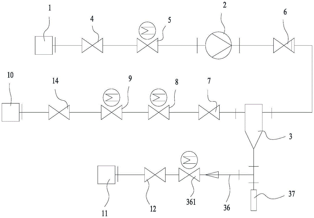
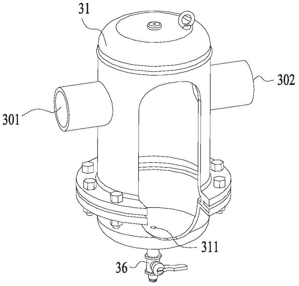
[0024] Such as Figure 1~4 The shown circulating water filter includes a first quick joint 1, a water pump 2, a filter 3 and a second quick joint 10 connected in sequence by pipelines. The filter 3 includes a relatively airtight housing 31, which is pivotally mounted on the housing 31. Inside the cylinder 32 and a plurality of spiral bars 33 spirally wound on the cylinder 32, the side wall of the housing 31 is provided with a filter inlet 301 and a filter outlet 302, the filter inlet 301 and the filter outlet 302 are coaxial, and the filter The inlet 301 communicates with the water pump 2, and the filter outlet 302 communicates with the second quick connector 10; the bottom wall of the housing 31 has a sewage outlet 311, and the sewage outlet 311 is connected with a sewage pipe 36, and the sewage pipe 36 is provided with a first electromagnetic valve 3...


PUM


Abstract

The invention discloses a circulating water filter. The circulating water filter comprises a first quick coupling, a water pump, a filter and a second quick coupling, which are connected in sequence through a pipeline, wherein the filter comprises a relatively closed shell, a cylinder which is pivoted in the shell and a plurality of spiral strips which are spirally coiled on the cylinder; a filter inlet and a filter outlet are formed in the side wall of the shell; the filter inlet and the filter outlet are coaxial; the filter inlet is communicated with the water pump; the filter outlet is communicated with the second quick coupling; a drain outlet which is connected with a drain pipe is formed in the bottom wall of the shell; a first electromagnetic valve is arranged on the drain pipe; a conductometer which is used for detecting the conductivity of the water in the shell is arranged on the side wall of the shell on one side of the drain outlet; the conductometer is in communication connection with the first electromagnetic valve. The circulating water filter is easy to maintain and strong in filter capability.

Description

technical field [0001] The invention relates to a filter, in particular to a circulating water filter. Background technique [0002] Industrial circulating water is mainly used in the cooling water system, so it is also called circulating cooling water, the purpose is to save water. Industrial circulating water is basically open and open-air. After long-term use, it is easy to produce a large amount of solid particle impurities such as dust, rust, and algae agglomeration. After these solid impurities are generated, if sewage treatment is not performed, the circulation will be blocked. pipeline, leading to the inoperability of the entire circulatory system. [0003] At present, most of the bypass water quality filtration equipment used for circulating water to remove solid particles in water use traditional filter screens and filter elements, or adopt activated carbon adsorption. After a period of filtration, the filter screens and filter elements will be used. If the filte...

Claims


Application Information

Patent Timeline
Patent Type & Authority Patents(China)
IPC IPC(8): B01D33/067B01D33/76B01D33/80
Inventor 王伟
Owner 广州蓝水环境设备科技有限公司
Why Eureka
Try Eureka