
A kind of rram sensitive amplifier

A technology of sense amplifier and reference branch, which is applied in the fields of instruments, static memory, digital memory information, etc., can solve the problems of increasing design implementation difficulty, decreasing memory data throughput, increasing chip power supply and ground width, and design difficulty, etc. Achieve the effect of reducing the layout and wiring width and design difficulty, reducing the layout and wiring width and design difficulty, and shortening the data reading cycle

Active Publication Date: 2017-04-12
XI AN UNIIC SEMICON CO LTD
View PDF11 Cites 0 Cited by
  • Summary
  • Abstract
  • Description
  • Claims
  • Application Information

AI Technical Summary

Problems solved by technology

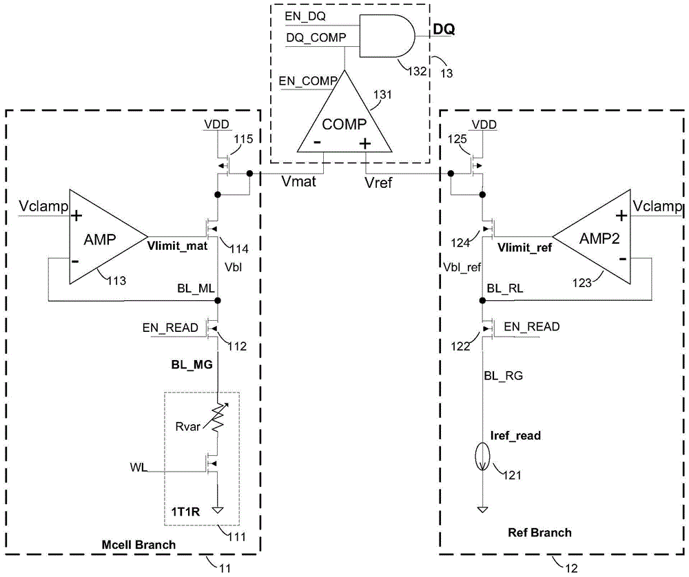
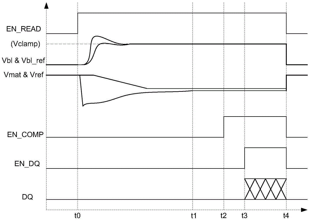
[0012] Although the above-mentioned existing solutions can successfully realize the reading function of the storage unit, there are still the following disadvantages: 1) The data reading speed is slow, mainly because the pre-charging phase (t0~t1) takes a long time, that is, Vmat stabilizes to the target value The time taken is too long, resulting in the lengthening of the entire data reading cycle, which in turn affects the decline in the data throughput of the memory; 2) There are many devices (including two op amps, a comparator and other circuits), and the layout area is large; especially for multiple The memory of byte (for example 16Bytes) operation will need more sense amplifiers (for example 128), so chip area is larger, and chip cost increases; 3) operating current is big, assuming the operating current of each amplifier and comparator is 50uA, and the operating current of other circuits is 20uA, then the operating current of a sense amplifier is about 170uA, and for a memory operated by multiple bytes (such as 16Bytes), the operating current is at least 128*170uA=21.8mA; at the same time, a large 4) There are many feedback loops (the storage branch and the reference branch each contain a feedback loop), the system instability increases, and the difficulty of design and implementation also increases

Method used


Image

  • A kind of rram sensitive amplifier
  • A kind of rram sensitive amplifier
  • A kind of rram sensitive amplifier

Examples


Embodiment Construction

[0031] The present invention will be further described in detail below in conjunction with specific embodiments, which are explanations of the present invention rather than limitations.

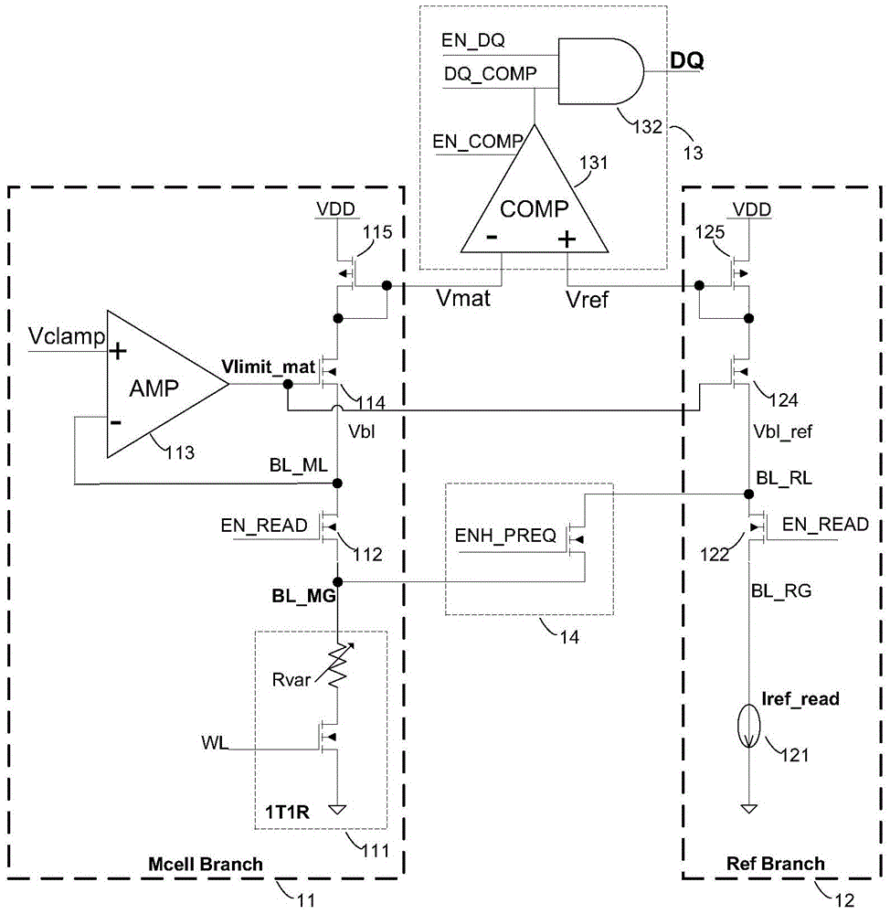
[0032] Such as image 3 Shown is a kind of RRAM sensitive amplifier of the present invention, as image 3As shown, it includes four parts: storage branch 11 , reference branch 12 , comparison output circuit 13 and precharge enhancement circuit 14 . The function of the storage branch 11 is to convert the state (high resistance state or low resistance state) of the variable resistance in the storage unit into a corresponding voltage signal Vmat; the function of the reference branch 12 is to convert the reference current into a corresponding reference voltage Vref; The function of the comparison output circuit 13 is to compare Vmat and Vref, and output the standard logic high and low levels corresponding to the low and high resistance states of the variable resistance; the function of the prech...


PUM


Abstract

A sense amplifier for a resistive random access memory comprises: a storage branch (11a), for converting the resistance value state of a variable resistor in a storage unit (111) into a corresponding voltage signal Vmat to output; a reference branch (12a), for converting a reference current into a corresponding reference voltage Vref to output; a comparison and output circuit (13), electrically connected to the storage branch (11a) and the reference branch (12a), so as to compare the voltage signal Vmat with the reference voltage Vref and output a data signal corresponding to a low or high resistance state of the variable resistor; and a pre-charging enhancement circuit (14, 14'), electrically connected between the storage branch (11a) and the reference branch (12a), so as to communicate the storage branch (11a) and the reference branch (12a) during a pre-charging stage. Also disclosed is a resistive random access memory comprising at least one sense amplifier.

Description

technical field [0001] The invention relates to the field of storage devices, in particular to an RRAM sensitive amplifier. Background technique [0002] Resistive random access memory (RRAM) is a new type of non-volatile information storage technology, which has the characteristics of simple structure, compatible with standard CMOS technology, low operating voltage, low power consumption and high-speed reading and writing. Its storage information unit is made of a metal oxide (such as CuO x , WO x ,HfO x , TiO x , NiO x etc.) realized variable resistors. Under different working conditions, the varistor exhibits bipolar memory characteristics of high resistance state (for example: 100Kohm) and low resistance state (for example: 10Kohm). [0003] Reading the stored information is to convert the state of the variable resistor (high resistance state and low resistance state) into a level signal (low level and high level) that can be recognized by the external circuit. Us...

Claims


Application Information

Patent Timeline
Patent Type & Authority Patents(China)
IPC IPC(8): G11C7/06
CPCG11C7/06
Inventor 谢永宜
Owner XI AN UNIIC SEMICON CO LTD
Learn More