Eureka AIR delivers breakthrough ideas for toughest innovation challenges, trusted by R&D personnel around the world.

Display panel assembly structure and display device

A display panel and assembly structure technology, applied in nonlinear optics, instruments, optics, etc., can solve the problems of increasing process and production costs, easy to break, product defects, etc., to simplify the connection process and eliminate flexible circuit boards. Fractures and the effect of reducing production costs

Active Publication Date: 2015-07-15
KUSN INFOVISION OPTOELECTRONICS
View PDF6 Cites 13 Cited by
  • Summary
  • Abstract
  • Description
  • Claims
  • Application Information

AI Technical Summary

Problems solved by technology

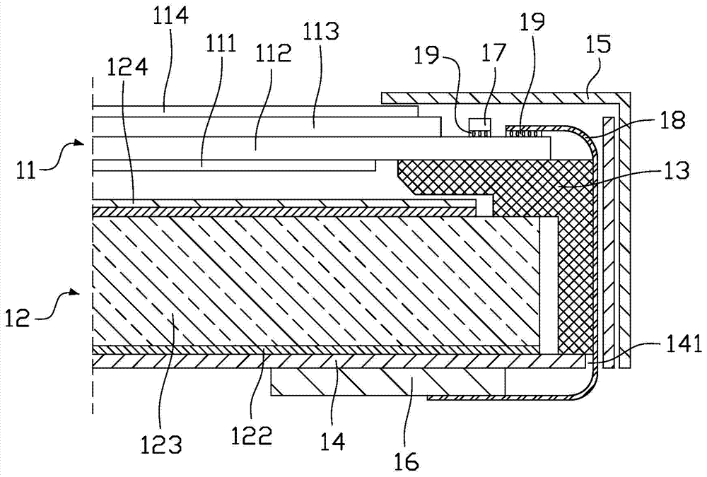
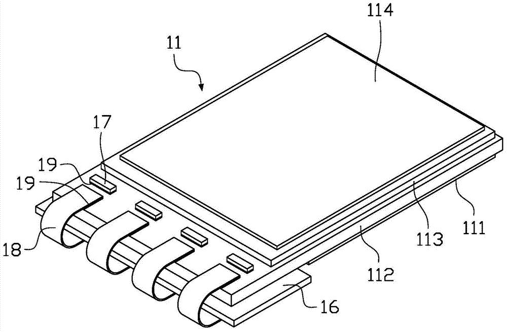
Therefore, an external lead bonding (Outer Lead Bonding, OLB) machine is required to bond the flexible circuit board 18 to the liquid crystal display panel 11, which increases the process and production costs; in addition, the flexible circuit board 18 is a flexible material, Fragile and easy to break, which can easily cause product defects

Method used


Image

  • Display panel assembly structure and display device
  • Display panel assembly structure and display device
  • Display panel assembly structure and display device

Examples


no. 1 example

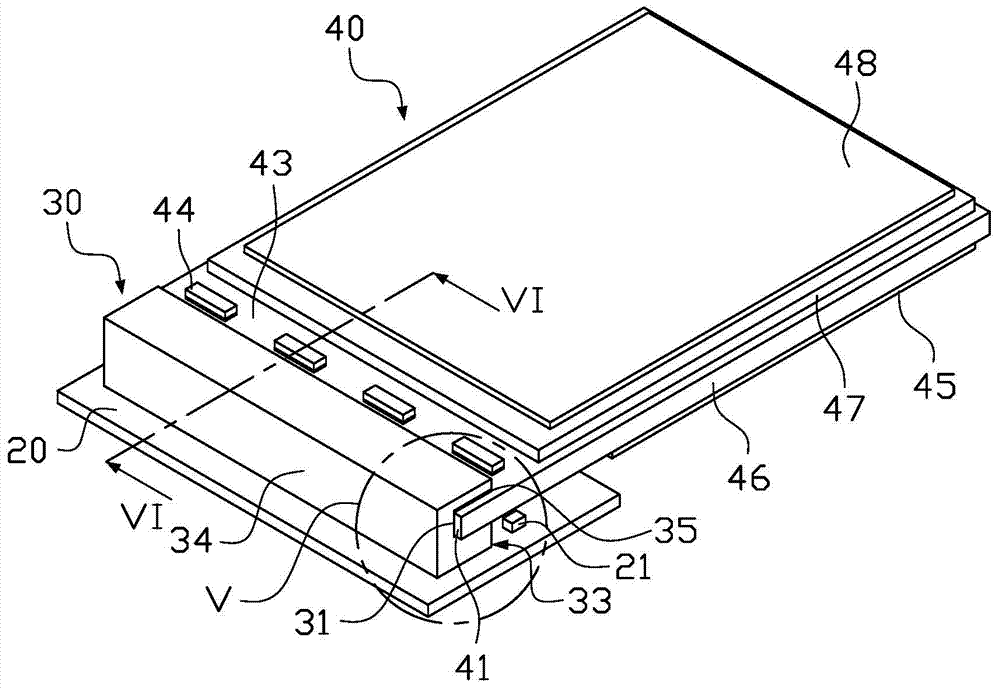
[0029] image 3 It is a structural schematic diagram of the assembly structure of the display panel in the first embodiment of the present invention, Figure 4 for image 3 Schematic diagram of the structure of the rigid circuit board in, Figure 5 for image 3 Schematic diagram of the enlarged structure of part V in the middle, Image 6 for image 3 The cross-sectional schematic diagram after being cut along the VI-VI line in , please combine Figure 3 to Figure 6 , The display panel assembly structure provided in this embodiment includes a rigid circuit board 20 , a connector 30 , and a display panel 40 . The connector 30 is fixed on the rigid circuit board 20 , and the connector 30 is provided with a slot 31 along a horizontal direction on a side surface close to the display panel 40 , and a plurality of probes 32 are provided in the slot 31 . The display panel 40 has an insertion end 41 on the side close to the connector 30, the insertion end 41 is provided with a pl...

no. 2 example

[0039] In the above first embodiment, the display panel 40 is a liquid crystal display panel as an example for illustration. However, in other embodiments of the present invention, the display panel 40 can also be other types of display panels, please refer to Figure 7 , Figure 7 It is a structural schematic diagram of the assembly structure of the display panel in the second embodiment of the present invention. In this embodiment, the display panel 40a is a flexible display panel, such as a flexible organic light emitting diode (Flexible Organic Light Emitting Diode) that is self-illuminating and does not need an additional backlight source. Light-Emitting Diode, FOLED) display panel, because the display panel 40a is flexible and rollable, it is suitable for making a flexible display device. The insertion end 41 of one side of the display panel 40a (refer to image 3 ) into the slot 31 of the connector 30a, through a plurality of probes 32 of the connector 30a (see Imag...


PUM


Abstract

The invention discloses a display panel assembly structure, which comprises a hard circuit board and a display panel, wherein an insertion end is arranged on one side of the display panel; a plurality of pins are arranged on the insertion end; the display panel assembly structure further comprises a connector fixed on the hard circuit board; the connector is provided with a slot in one lateral surface leaning against the display panel along the horizontal direction; a plurality of probes are arranged in the slot; the insertion end is fixedly inserted into the slot; the plurality of probes are respectively connected to the plurality of pins. According to the display panel assembly structure, the connector replaces the existing flexible circuit board, and the flexible circuit board is not in need of use, so that a process for jointing the flexible circuit board to the display panel by utilizing an OLB (Outer Lead Bonding) machine table is eliminated, and a processing for connecting the hard circuit board and the display panel is simplified, the production cost is reduced, and meanwhile, the broken phenomenon of the flexible circuit board due to application of the flexible circuit board is completed avoided.

Description

technical field [0001] The present invention relates to the field of display technology, in particular to a display panel assembly structure and a display device having the display panel assembly structure. Background technique [0002] With the rapid development of electronic products towards lightness, thinness and miniaturization, almost all kinds of portable electronic products use liquid crystal displays (Liquid Crystal Display, LCD) as display terminals, especially in camcorders, notebook computers, desktops, etc. In products such as computers, smart TVs, mobile terminals, and personal digital processors, liquid crystal displays are already important components. [0003] figure 1 It is a schematic diagram of a partial structure of an existing liquid crystal display device, please refer to figure 1 , The liquid crystal display device includes a liquid crystal display panel 11 , a backlight module 12 , a plastic frame 13 , a back plate 14 , and a front frame 15 and is ...

Claims


Application Information

Patent Timeline
IPC IPC(8): G02F1/1333G02F1/1345G02F1/13357
CPCG02F1/13306G02F1/13452G02F1/133325
Inventor 陆敏任亮亮
Owner KUSN INFOVISION OPTOELECTRONICS
Why Eureka
Eureka Blog
Learn More