Eureka AIR delivers breakthrough ideas for toughest innovation challenges, trusted by R&D personnel around the world.

Electrical machine

A technology of electrical connection and electrical joint, applied in the direction of synchronous generators, electrical components, electromechanical devices, etc., can solve disadvantages and other problems, and achieve the effect of small gap size and compact structure

Inactive Publication Date: 2009-12-02
SEG AUTOMOTIVE GERMANY GMBH
View PDF4 Cites 0 Cited by
  • Summary
  • Abstract
  • Description
  • Claims
  • Application Information

AI Technical Summary

Problems solved by technology

For generators of significantly higher power, such a construction is disadvantageous, since the guide pockets for the stator wires described in EP 0 329 722 B1 significantly block the rectifier cooling body from radially outer to radially inner Cooling air passing by or its cooling air path

Method used


Image

  • Electrical machine
  • Electrical machine
  • Electrical machine

Examples


Embodiment Construction

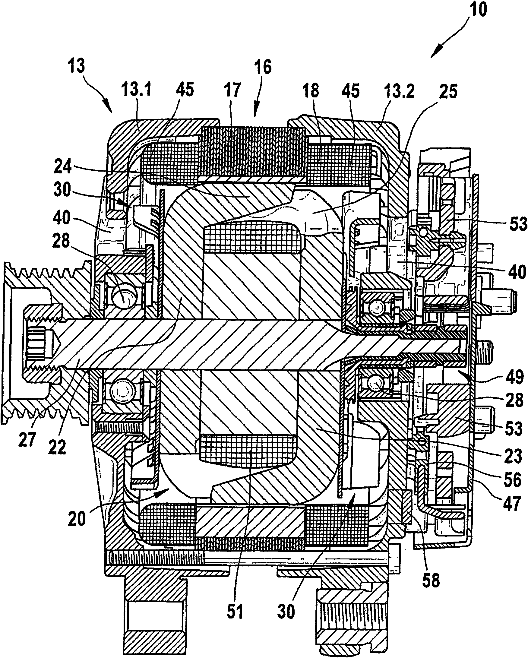
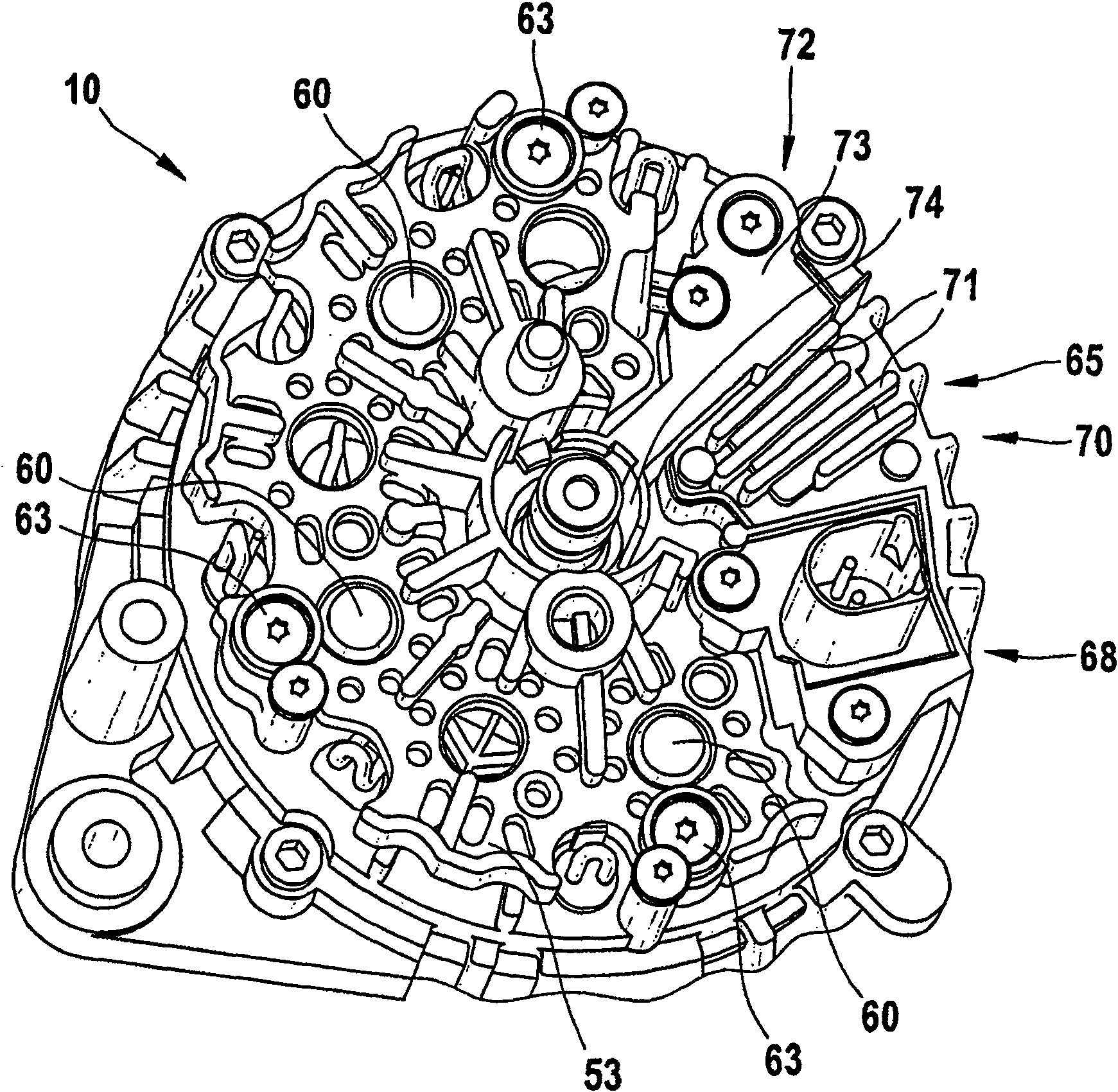
[0023] exist figure 1 A cross-sectional view of an electric machine 10, here a generator or alternator for a motor vehicle, is shown in . The electric machine 10 also has a two-part housing 13 comprising a first bearing shield 13.1 and a second bearing shield 13.2. The bearing shield 13.1 and the bearing shield 13.2 are fastened in a so-called stator 16, which on the one hand comprises an essentially circular stator core 17, and in its radially inwardly directed, axially extending grooves A stator winding 18 is embedded. The annular stator 16 surrounds with its radially inwardly directed slotted surface a rotor 20 which is formed as a claw pole rotor. The rotor 20 also includes two claw pole plates 22 and 23 , and claw pole fingers 24 and 25 extending in the axial direction are respectively arranged on the outer circumference thereof. The two claw pole plates 22 and 23 are arranged in the rotor 20 such that their axially extending claw pole fingers 24 or 25 alternate with e...


PUM


Abstract

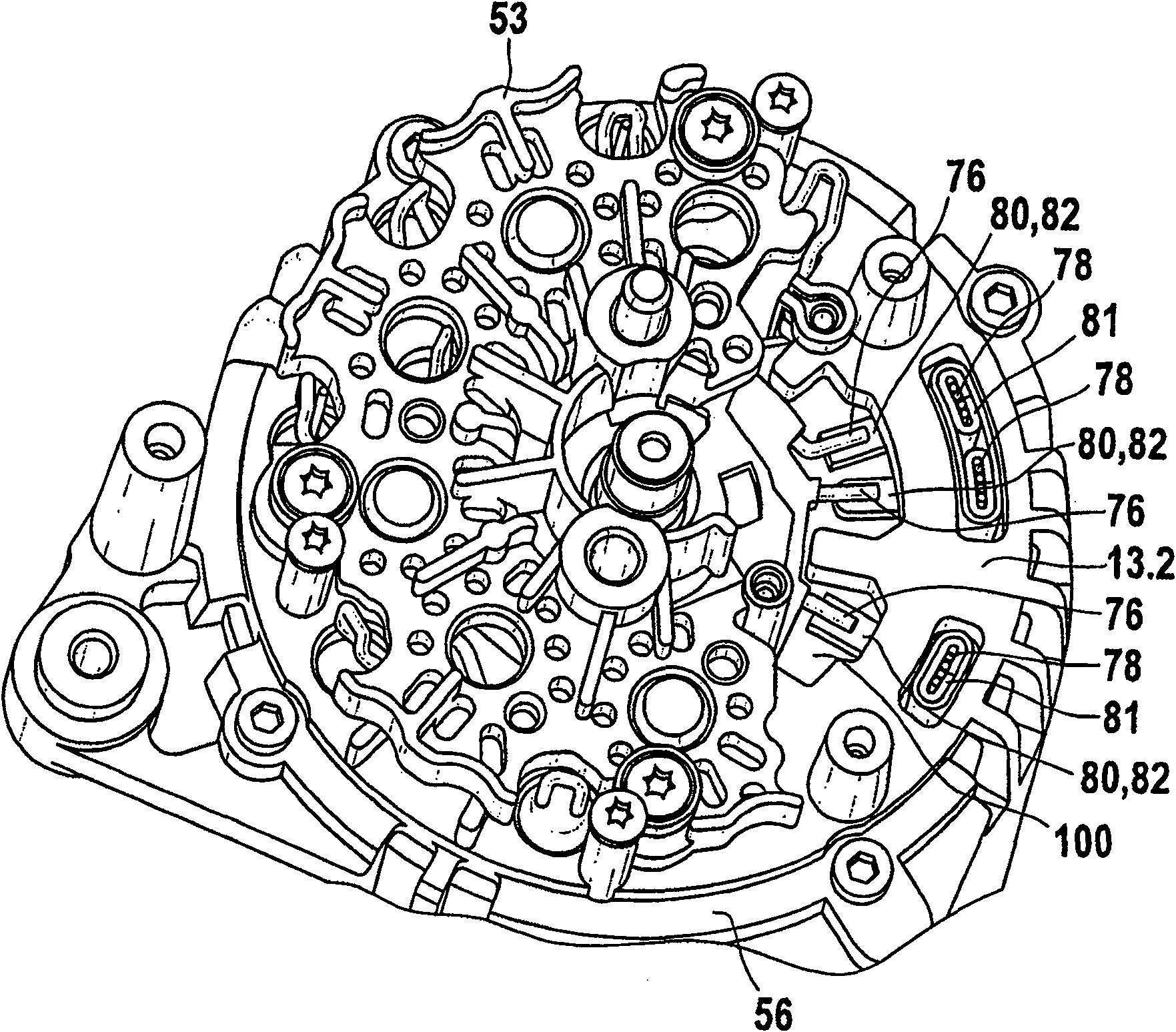
An electric machine, in particular an alternator for a motor vehicle, having a stator (16) supporting a stator winding (18), wherein the stator winding (18) has winding ends (78), the electric machine also has a regulator structure assembly (65) and a rectifier. The electrical connection between the winding head (78) and the rectifier is located below the regulator assembly (65). Furthermore, a stator for an electric machine, in particular for an alternator of a motor vehicle, is proposed, which has a stator winding (18), wherein the stator winding (18) has winding ends (78). In this case, the winding head (78) is connected to an additional conductor part (80), which joins the individual conductors of the winding head (78) via a clip-shaped connection area (81), and is a thin plate part.

Description

technical field [0001] The invention relates to an electric machine and a stator for such an electric machine. Background technique [0002] An electrical machine, which is here an alternator for a car, is known, for example, from the Fascicle "Generatoren Ausgabe (Generator Journal) 98 / 99" of the "Technische Unterrichtung (Technical Report)" series by Robert Bosch in 1998. , see also page 22 of this document. Such an electric machine has a stator, which supports a stator winding, the ends of which are connected directly to a rectifier or a regulator. A generator is also known, for example, sold by the company Bosch, which has, for example, standard part No. 0120 485 022 and which was commissioned, for example, in 1992. Such generators have a stator which supports a stator winding with winding ends. A rectifier, which is known from the patent literature, is arranged on one end of the generator, ie on the end opposite the drive pulley, under a protective cover. Such a rec...

Claims


Application Information

Patent Timeline
Patent Type & Authority Patents(China)
IPC IPC(8): H02K3/50H02K11/04H02K19/36
CPCH02K3/50H02K2203/03H02K11/046H02K11/05
Inventor A·埃尔泽尔T·伯格尔U·克纳彭伯格尔
Owner SEG AUTOMOTIVE GERMANY GMBH
Why Eureka
Eureka Blog
Learn More