Eureka AIR delivers breakthrough ideas for toughest innovation challenges, trusted by R&D personnel around the world.

Floor board panel

A floor paneling and edge technology, which is applied in the direction of thin plate connection, floor, connection components, etc., can solve the problems of connection edge manufacturing technology difficulties, connection edge height clamping, wear and other problems, and achieve good force distribution and force distribution, Smooth joining process, good self-centering effect

Inactive Publication Date: 2003-07-02
克罗诺泰克斯木材及合成树脂材料进出口有限公司
View PDF1 Cites 0 Cited by
  • Summary
  • Abstract
  • Description
  • Claims
  • Application Information

AI Technical Summary

Problems solved by technology

In addition, not only the abutting edge arranged on the connecting edge must ensure a good sealing effect, but also a good sealing effect against the foundation. In some cases, this will cause problems, and from the perspective of development trends, in the first In the lower range between the lower protrusion of one connecting edge and the tongue of the second connecting edge results in a high degree of jamming of the two connecting edges
In addition, in the case of complex shapes, especially in the recess, the production of the connection edge is generally difficult in terms of production technology, especially the milling guides required for forming the connection edge are very complex, This leads to higher wear in the complex guiding range

Method used


Image

  • Floor board panel
  • Floor board panel
  • Floor board panel

Examples


Embodiment Construction

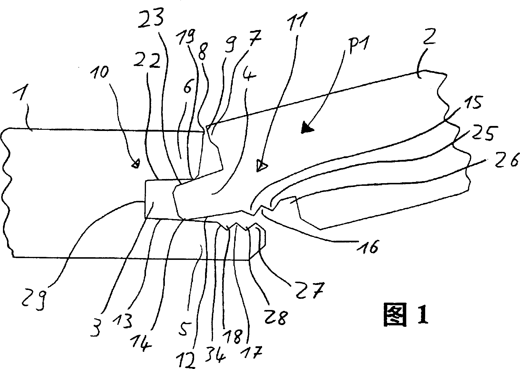
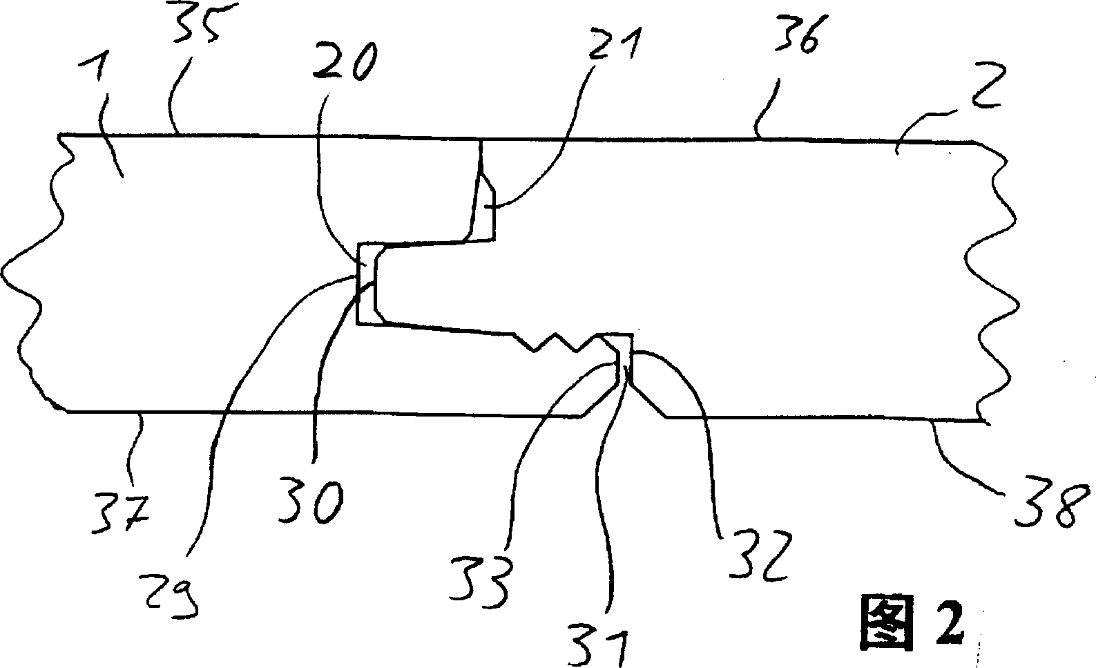
[0025] According to FIG. 5 , a connecting panel 1 has a first connecting edge 10 and, on the opposite side, a second connecting edge 11 . Here, the two connecting edges are formed in such a way that they are matched to each other for interlocking insertion, as shown in FIGS. 1 and 2 . Here, the first connecting edge 10 of the floor panels 1 has an upper projection 6 , a lower projection 5 and a groove 3 between the two projections. An abutment edge 8 is formed at the upper end of the upper extension 6 . Groove 3 has a groove bottom 29, is surrounded by the upper surface 13 of lower extension 5 and the bottom surface 22 of upper extension 6, and here, the bottom surface 22 of upper extension 6 and the upper surface 13 of lower extension 5 face The groove bottom 29 extends obliquely, so that the groove 3 tapers gradually in the direction of the groove bottom 29 . A connecting profile is formed at the outer end of the lower projection 5 , which has a lower bead 27 and a lower g...


PUM


Abstract

Flooring panel with two connection members whose sides face each other for attachment to other flooring panels of the same type. A first connection member has an upper projection, a lower projection, and groove between them. A second connecting member features a tongue for insertion in the groove of an adjacent connection member. In order to achieve good assembly as well as economical production of the panels, provision is made for a lower protuberance, lower indentation, lower auxiliary protuberance, and lower auxiliary indentation on the lower projection of the first connection member. The profile thus created is fitted to a corresponding profile on the lower side of the tongue which has an upper indentation, an upper protuberance, an upper auxiliary indentation, and an upper auxiliary protuberance. The floor panel is excellent in sealing function and can be costlessly manufactured with less labor.

Description

technical field [0001] The invention relates to a floor panel. Background technique [0002] One such floor panel is known from WO 97 / 47834 A1 FIGS. 5 to 7 or 22 to 25 . A plurality of such floor panels can be joined to one another without having to glue them, for example, to the foundation or to connect them to one another by means of additional connecting elements, such as strips. Here, for example, the connecting edges of two floor panels can be joined together by sliding one another in a straight line parallel to the foundation, wherein in this case, in order to achieve a form fit between the connecting edges, the first The lower projection of the connecting edge must be bent downwards, and then due to its elastic action, the lower projection returns to its original position, and at this time hooks the upper projection on the underside of the tongue, so that , the two connecting edges will not be separated again due to a simple straight line outward pulling, and the se...

Claims


Application Information

Patent Timeline
Patent Type & Authority Patents(China)
IPC IPC(8): E04F15/02E04F15/04F16B5/00
CPCE04F15/04E04F2201/0115F16B5/008E04F2201/0153B29C48/07B29C48/0011
Inventor 德特勒夫·蒂克森
Owner 克罗诺泰克斯木材及合成树脂材料进出口有限公司
Why Eureka
Eureka Blog
Learn More