
Synchronous shutdown LED boost driving circuit

A technology for driving circuits and LED light sources, applied in the field of lighting, can solve the problems of low circuit energy utilization and slow response.

Active Publication Date: 2015-07-08
SHENZHEN OCEANS KING LIGHTING ENG CO LTD +1
View PDF10 Cites 1 Cited by
  • Summary
  • Abstract
  • Description
  • Claims
  • Application Information

AI Technical Summary

Problems solved by technology

[0004] Based on this, it is necessary to provide a synchronous turn-off LED boost drive circuit with high energy utilization and rapid response for the problem of low energy utilization and slow response of the circuit.

Method used


Image

  • Synchronous shutdown LED boost driving circuit
  • Synchronous shutdown LED boost driving circuit
  • Synchronous shutdown LED boost driving circuit

Examples


Embodiment Construction

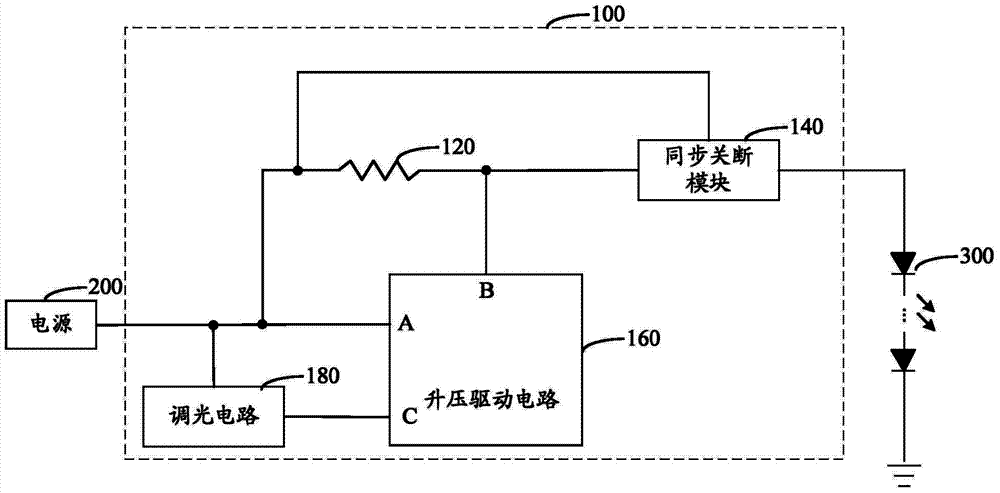
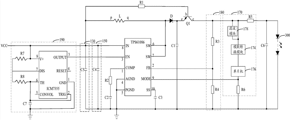
[0023] A synchronous turn-off LED boost drive circuit, which separates the energy storage stage of the inductor from the discharge stage. During the energy storage stage of the inductor, it will not discharge to the load at all, which improves the energy storage rate of the circuit and makes the inductor in the discharge stage The energy is not reduced, correspondingly, the response speed of the circuit is improved, and the LED light source is lit up faster. The pulse width modulation signal with adjustable amplitude is output by the dimming circuit to realize the adjustable current of the main loop, so that the brightness of the LED light source can be adjusted. Moreover, the above-mentioned synchronous turn-off LED boost drive circuit uses the TPS61-86 chip to realize the protection functions of overvoltage, undervoltage and overheating.

[0024] In order to make the object, technical solution and advantages of the present invention clearer, the present invention will be fur...


PUM


Abstract

The invention discloses a synchronous shutdown LED boost driving circuit comprising an inductor, a synchronous shutdown module, a boost driving circuit, and a dimming circuit. When the boost driving circuit is not started, the inductor stores energy, the synchronous shutdown module is in an open state, and a loop is open. When the boost driving circuit is started, the inductor discharges electricity, the synchronous shutdown module is in a closed state, the loop is closed, and an LED light source is energized and lighted up. Based on dimming signals output by the dimming circuit, the boost driving circuit outputs different voltage signals, the magnitude of current on a main loop is changed, and the brightness of the LED light source is changed. The energy storage period and the discharge period of the inductor are separated by the synchronous shutdown module. In the energy storage period of the inductor, the inductor does not discharge electricity to a load at all. Thus, the energy utilization rate of the circuit is increased, and the energy of the inductor is not reduced in the discharge period. Adjustment of the brightness of the LED light source is realized, and the scope of application of the LED light source is expanded. The synchronous shutdown LED boost driving circuit is convenient and practical.

Description

technical field [0001] The invention relates to the field of lighting technology, in particular to a synchronously turned off LED boost drive circuit. Background technique [0002] A light-emitting diode (Light-Emitting Diode, LED) is a semiconductor electronic component that can emit light. Diodes made of gallium, arsenic, and phosphorus compounds can radiate visible light when electrons and holes recombine, so they can be used to make light-emitting diodes. It is used as an indicator light in circuits and instruments, or as a text or number display. With the continuous advancement of technology, light-emitting diodes have been widely used in displays, TV lighting decoration and lighting. [0003] The power supply circuit of the traditional LED is powered by a battery and needs a boost circuit to drive it. A traditional boost drive circuit includes an energy storage circuit and an energy consumption circuit. The energy storage circuit is generally an inductor, and the e...

Claims


Application Information

Patent Timeline
Patent Type & Authority Applications(China)
IPC IPC(8): H05B37/02
Inventor 周明杰刘百顺
Owner SHENZHEN OCEANS KING LIGHTING ENG CO LTD
Learn More