
High-current live down lead component of overhead line and operating mechanism of high-current live down lead component

An operating mechanism and overhead line technology, applied in the direction of overhead line/cable equipment, line/collector parts, electrical components, etc., can solve the problems of not clamping the wire tightly, jamming, affecting power supply, etc.

Active Publication Date: 2015-07-01
STATE GRID CORP OF CHINA +2
View PDF6 Cites 7 Cited by
  • Summary
  • Abstract
  • Description
  • Claims
  • Application Information

AI Technical Summary

Problems solved by technology

The above two operations will use the down conductor component, but the current structure of the down conductor component is generally that the screw pushes the slider to move up and down along the track inside the frame body, and the rotation of the screw may cause the slider to also produce a certain In this way, the phenomenon of jamming may occur during the upward and downward movement of the slider, the assembly and disassembly operation is difficult, and the high-voltage operation of the staff is unsafe; in addition, the wire may not be clamped tightly and flashover may occur, which affects the power supply

Method used


Image

  • High-current live down lead component of overhead line and operating mechanism of high-current live down lead component
  • High-current live down lead component of overhead line and operating mechanism of high-current live down lead component
  • High-current live down lead component of overhead line and operating mechanism of high-current live down lead component

Examples


Embodiment Construction

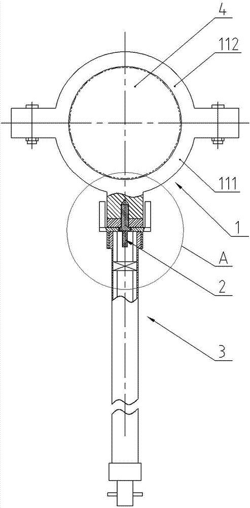
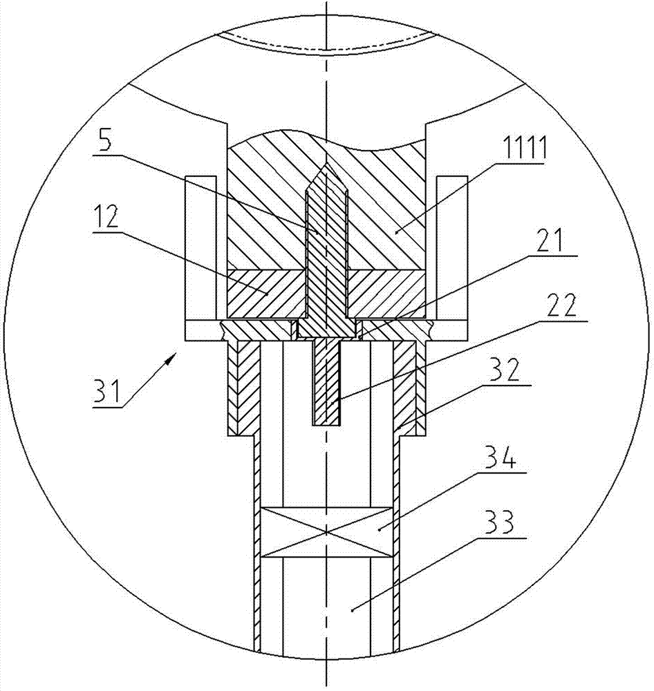
[0021] Such as Figure 1 to Figure 5 As shown, the present invention discloses a high-current live down-conductor component of an overhead line and its operating mechanism, including a down-conductor component 1 , a sleeve mold 2 and an operating mechanism 3 .

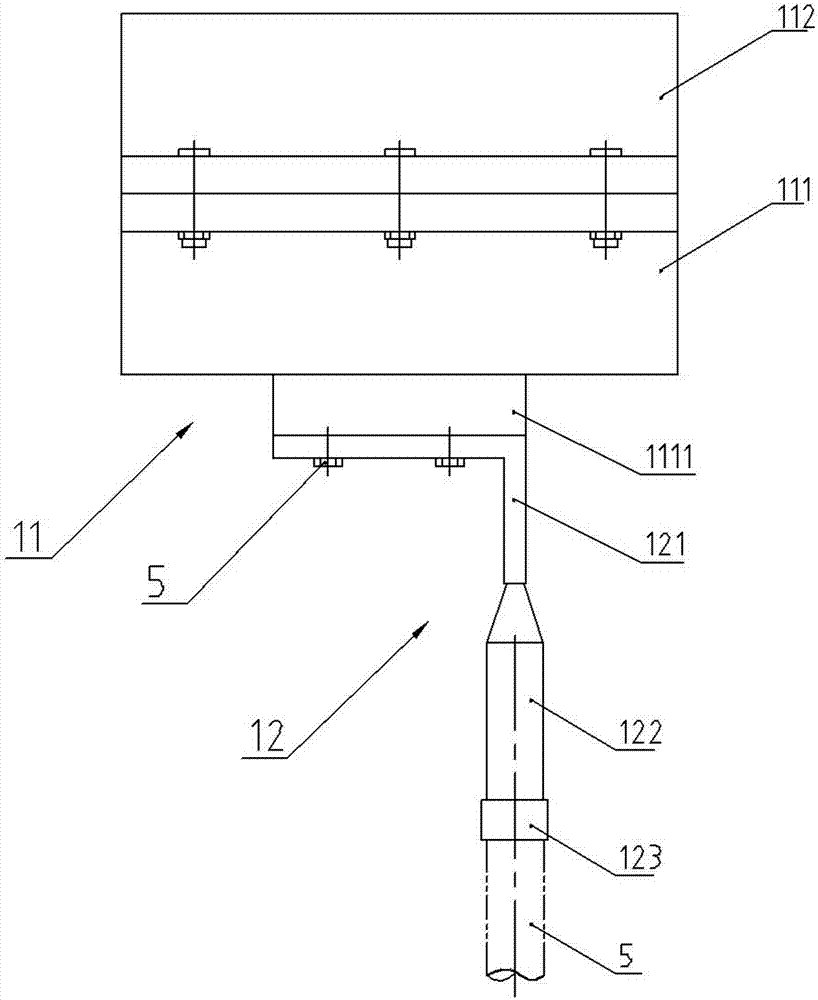
[0022] The down conductor member 1 includes a branch clamp 11 and a lug 12 . The branch wire clamp 11 has an upper and lower split structure, including a wire support plate 111 and a cover plate 112 that cooperate with each other. The middle section of the cross-section of the cover plate 112 and the thread support plate 111 is an outwardly protruding circular arc segment, and the two sides are connecting flanges. Butt holes are arranged on the connecting flange along the length direction, and the two circular arc segments cover the busbar 4. The cover plate 112 and the thread support plate 111 are connected and fastened by bolts passing through the butt holes and corresponding nuts. There is a protruding platform 11...


PUM


Abstract

The invention discloses a high-current live down lead component of an overhead line and an operating mechanism of the high-current live down lead component. The high-current live down lead component comprises a branch clamp and a connection lug. The branch clamp comprises a support plate and a cover plate which are vertically butted to each other, the connection lug is connected with the lower side of the support plate by screws, and connecting screw holes are formed in the lower side of the support plate. The operating mechanism comprises a fixture, a support operating rod and a spiral propulsion operating rod. The support operating rod is a hollow circular pipe, the spiral propulsion operating rod is assembled in the clamp support operating rod and can move up and down, the fixture is connected to the upper end of the support operating rod, a sleeve mold which penetrates the fixture and is used for tightening the screws is connected to the upper end of the spiral propulsion operating rod, the support plate can be clamped by the fixture, so that the sleeve mold can prevent the support plate from rotating when the connection lug and the support plate are connected and fastened by the screws. The high-current live down lead component and the operating mechanism have the advantages that the branch clamp and buses are large in contact area, connection between corresponding components is stable in mechanical performance, accordingly, the power supply safety can be improved, and the branch clamp can be conveniently and quickly mounted and detached by the operating mechanism.

Description

technical field [0001] The invention relates to a live down conductor device on a large current transmission line, in particular to a live down conductor component and its operating mechanism on a large current transmission line. Background technique [0002] When there is a problem with the equipment on the transmission line and needs to be overhauled, the branch power supply must be disconnected to ensure safe overhaul. In order to ensure the operation of the grid, sometimes live switching branches are required. The above two operations will use the down conductor component, but the current structure of the down conductor component is generally that the screw pushes the slider to move up and down along the track inside the frame body, and the rotation of the screw may cause the slider to also produce a certain In this way, the phenomenon of jamming may occur during the upward and downward movement of the slider, the assembly and disassembly operation is difficult, and the...

Claims


Application Information

Patent Timeline
Patent Type & Authority Applications(China)
IPC IPC(8): H01R11/01H01R11/05H01R4/20H01R4/46H01R43/00H02G1/02
CPCH01R4/20H01R4/46H01R11/01H01R11/05H01R43/00H02G1/02
Inventor 邓晓廉龚爱国肖德祥刘军志
Owner STATE GRID CORP OF CHINA
Learn More