
Efficient heat-dissipation LED (Light-Emitting Diode) stage lamp

A high-efficiency technology for LED stage lights, applied in lighting and heating equipment, parts of lighting devices, semiconductor devices of light-emitting elements, etc., can solve the problem of LED chip heat dissipation affecting the large-scale promotion and use of LED stage lights, damaging lamps, and affecting use Life and other issues, to achieve the effect of easy disassembly, use and maintenance, simple use method, and improved heat dissipation

Inactive Publication Date: 2015-07-01
杜志刚
View PDF3 Cites 1 Cited by
  • Summary
  • Abstract
  • Description
  • Claims
  • Application Information

AI Technical Summary

Problems solved by technology

[0002] Stage light is a high-power lighting device used in stages, karaoke halls and other places to beautify and enhance the stage effect. In recent years, with the continuous maturity of LED technology, LED light source has been gradually applied to the field of stage lights. The luminous efficiency of LED lights is high. , with good light stability, has been widely used in stage light effect lighting. At the same time, as a professional lighting equipment, stage lights have put forward variability requirements for spotlight effects and light patterns in order to meet different lighting needs. However, LED The chip will generate heat during the light emitting process, and the high-power LED lamp will cause the internal temperature of the LED chip to rise too fast during the light emitting process, generating a large amount of heat, affecting its service life, and even damaging the lamp. The heat dissipation problem of the LED chip seriously affects the Large-scale promotion and use of LED stage lights

Method used


Image

  • Efficient heat-dissipation LED (Light-Emitting Diode) stage lamp
  • Efficient heat-dissipation LED (Light-Emitting Diode) stage lamp

Examples


Embodiment Construction

[0012] The following will clearly and completely describe the technical solutions in the embodiments of the present invention with reference to the accompanying drawings in the embodiments of the present invention. Obviously, the described embodiments are only some, not all, embodiments of the present invention. Based on the embodiments of the present invention, all other embodiments obtained by persons of ordinary skill in the art without making creative efforts belong to the protection scope of the present invention.

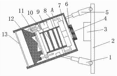
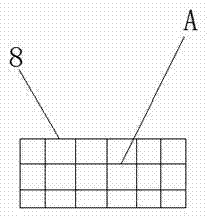
[0013] see figure 1 , the present invention provides a technical solution: a high-efficiency heat dissipation LED stage lamp, including a first electric telescopic arm 1, a fixed plate 2, a control box 3, an air filter 4, a second electric telescopic arm 5, a vent 6, Exhaust fan 7, shell 8, adjuster 9, radiator 10, light source 11, lens 12 and convex mirror 13, one end of the first electric telescopic arm 1 and the second electric telescopic arm 5 are all conn...


PUM


Abstract

The invention discloses an efficient heat-dissipation LED (Light-Emitting Diode) stage lamp. The efficient heat-dissipation LED stage lamp comprises a first electric telescopic arm, a fixing plate, a control box, an air filter, a second electric telescopic arm, a ventilation opening, an exhaust fan, a shell, a regulator, a radiator, a light source, a lens and a convex mirror, wherein one end of the first electric telescopic arm and one end of the second electric telescopic arm are connected with the fixing plate; one end of the first electric telescopic arm and one end of the second electric telescopic arm are fixed on the shell; the ventilation opening is formed in the back end of the shell; the air filter is positioned outside the ventilation opening; the exhaust fan is arranged at the bottom end of the radiator; the regulator is positioned above the radiator; the light source and the lens are arranged on one side which is positioned on an illuminator of the radiator; the convex mirror is arranged at one end of the shell. The efficient heat-dissipation LED stage lamp is simple in structure, is reasonable in layout, and meets multi-aspect use of a stage; the heat dissipation performance of the LED stage lamp can be enhanced, and upward and downward swinging of the stage lamp can be realized.

Description

technical field [0001] The invention relates to the technical field of stage equipment, in particular to an efficient heat dissipation LED stage lamp. Background technique [0002] Stage light is a high-power lighting device used in stages, karaoke halls and other places to beautify and enhance the stage effect. In recent years, with the continuous maturity of LED technology, LED light source has been gradually applied to the field of stage lights. The luminous efficiency of LED lights is high. , with good light stability, has been widely used in stage light effect lighting. At the same time, as a professional lighting equipment, stage lights have put forward variability requirements for spotlight effects and light patterns in order to meet different lighting needs. However, LED The chip will generate heat during the light emitting process, and the high-power LED lamp will cause the internal temperature of the LED chip to rise too fast during the light emitting process, gene...

Claims


Application Information

Patent Timeline
Patent Type & Authority Applications(China)
IPC IPC(8): F21S8/00F21V21/22F21V29/67F21W131/406F21Y101/02F21Y115/10
CPCF21S8/00F21V21/22F21W2131/406
Inventor 杜志刚
Owner 杜志刚
Learn More