A double-layer automatic sand leveling equipment
An automatic, flat-sand technology, used in metal processing equipment, grinding/polishing equipment, abrasive belt grinders, etc., can solve the impact of the service life of the abrasive belt, the impact on the transmission performance of the abrasive belt, the high temperature of the first roller and the second roller Overheating and other problems, to achieve the effect of improving polishing efficiency, high grinding efficiency and improving transmission performance
- Summary
- Abstract
- Description
- Claims
- Application Information
AI Technical Summary
Problems solved by technology
Method used
Image
Examples
Embodiment 1
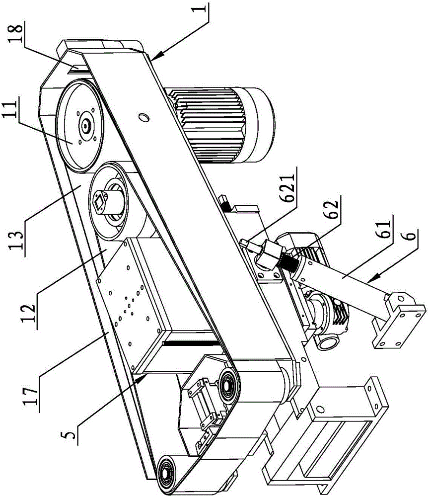
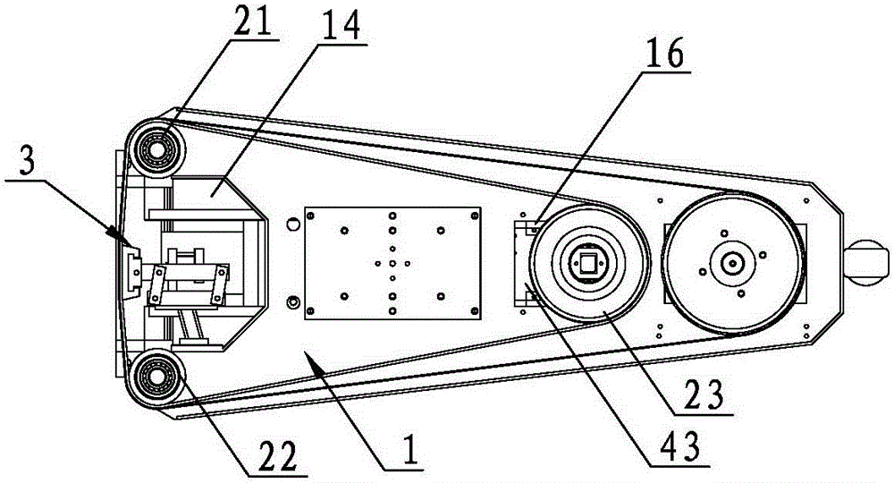
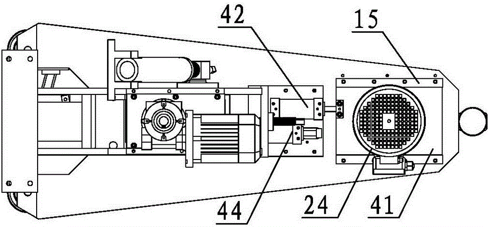
[0043] see Figure 1 to Figure 8 , a double-layer automatic sand leveling equipment, including a carrier substrate 1, the carrier substrate 1 is respectively provided with a driving roller 11, a first driven roller 21, a second driven roller 22 and a first driving roller 11 for driving the driving roller 11. A motor 24, the carrier substrate 1 is also provided with a third driven roller 23, the third driven roller 23, the first driven roller 21 and the second driven roller 22 are connected to each other through the lining belt 12, and the The driving roller 11 is transmission-connected to the backing belt 12 on the outside of the first driven roller 21 and the second driven roller 22 through an abrasive belt 13, and the bearing substrate 1 is also provided with a pressing device 3 for pressing against the backing belt 12 . The working principle of this automatic flat sand equipment is: the first motor 24 drives the driving roller 11 to rotate, because the lining belt 12 is se...
Embodiment 2
[0053] see Figure 9 The difference between this embodiment and Embodiment 1 is that: the carrier substrate 1 is provided with a concave position 14 for accommodating the pressure applying device 3 , and the pressure applying device 3 includes a fixing device fixedly connected with the concave position 14 arm 31, the fixed arm 31 is equipped with a fixed plate 32, the fixed plate 32 is provided with a first cylinder 35, the end of the piston rod of the first cylinder 35 is connected with a buttress for pressing the lining belt 12 Press block 34. When working, the first cylinder 35 directly drives the pressing block 34 to press against the backing belt 12 , and the structure of the pressing device 3 in this embodiment is simpler and easier to manufacture.
[0054] Other parts of this embodiment are the same as those of Embodiment 1, and will not be repeated here.
Embodiment 3
[0056] see Figure 10 , the difference between this embodiment and Embodiment 1 is that: the pressing device 3 includes a movable arm 36, one end of the movable arm 36 is hinged to the carrier substrate 1 and is provided with a return spring 37, and the movable arm 36 is set There is a pressing block 34 for pressing against the lining strip 12 , and the other end of the movable arm 36 extends outward to form an operating handle 38 . When the pressing device 3 of this embodiment is working, the operator manually controls the operating handle 38 so that the pressing block 34 is pressed against the lining belt 12. In this embodiment, the manual method can greatly save the manufacturing cost of the equipment. And easy to maintain.
[0057] Other parts of this embodiment are the same as those of Embodiment 1, and will not be repeated here.
PUM
 Abstract
Description
Claims
Application Information
 - R&D
- Intellectual Property
- Life Sciences
- Materials
- Tech Scout
- Unparalleled Data Quality
- Higher Quality Content
- 60% Fewer Hallucinations
Browse by: Latest US Patents, China's latest patents, Technical Efficacy Thesaurus, Application Domain, Technology Topic, Popular Technical Reports.
© 2025 PatSnap. All rights reserved.Legal|Privacy policy|Modern Slavery Act Transparency Statement|Sitemap|About US| Contact US: help@patsnap.com


