Eureka AIR delivers breakthrough ideas for toughest innovation challenges, trusted by R&D personnel around the world.

Anti-collision structure of submerged floating tunnel

A technology for floating and floating tunnels in water, which is applied to underwater structures, infrastructure engineering, water conservancy projects, etc. It can solve the problems that there are no relevant reports on the safety of floating tunnel structures, the safety of floating tunnels is difficult to be guaranteed, and the absorption of impact energy Capability is limited and other problems, to achieve the effect of convenient and quick installation and disassembly, saving engineering maintenance costs, and strong energy absorption capacity

Inactive Publication Date: 2015-06-24
CHINA MERCHANTS CHONGQING COMM RES & DESIGN INST +1
View PDF7 Cites 16 Cited by
  • Summary
  • Abstract
  • Description
  • Claims
  • Application Information

AI Technical Summary

Problems solved by technology

In the absence of special safety protection, if there is a sudden marine accident: such as shipwreck, crash, etc., it may directly hit the floating tunnel and cause damage
Among the existing protective measures, although the aluminum casing is wrapped on the outer wall of the tunnel, it has a certain anti-collision effect, but its ability to absorb impact energy is very limited. If it encounters a heavy shipwreck, the safety of the floating tunnel cannot be guaranteed. The safety of floating tunnel structures under impact loads has not been reported so far

Method used


Image

  • Anti-collision structure of submerged floating tunnel
  • Anti-collision structure of submerged floating tunnel
  • Anti-collision structure of submerged floating tunnel

Examples


Embodiment Construction

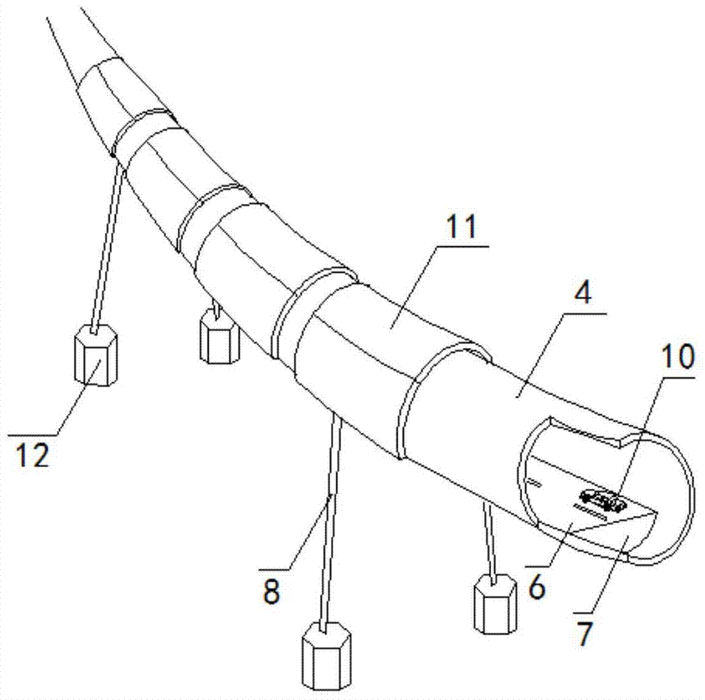
[0024] see figure 1 and figure 2 In this embodiment, the anti-collision structure of the floating tunnel in water is the anti-collision and energy-dissipating sleeve covering the outer wall 4 of the floating tunnel. , the interval between adjacent anti-collision pipe sections 11 is 0.3-0.6m.

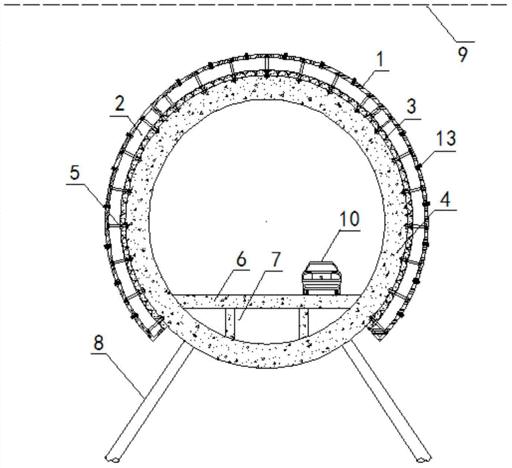
[0025] Such as image 3 As shown, in the present embodiment, the anti-collision pipe section 11 is arranged on the outer wall 4 of the floating tunnel as fan-shaped segments along the circumference. , each segment and the outer wall 4 of the floating tunnel are fixedly connected by high-strength bolts 5, and the axial direction refers to the passing direction of the floating tunnel in the water; each segment is a multi-layer composite structure, and the multi-layer composite structure includes a polyurethane elastic panel on the surface 1 and the energy-dissipating cushion 3 that is in the inner layer and is closely attached to the pipe wall 4 of the floating tunnel. A closed pressur...


PUM

PropertyMeasurementUnit
hardnessaaaaaaaaaa

Abstract

The invention discloses an anti-collision structure of a submerged floating tunnel. The anti-collision structure of the submerged floating tunnel is characterized in that the anti-collision structure is composed of anti-collision energy dissipation casing pipes covering the outer wall of the floating tunnel, anti-collision pipe sections capable of being disassembled and assembled independently are arranged on the axial section of the anti-collision energy dissipation casing pipes, the anti-collision pipe sections are pipe pieces arranged on the outer wall of the floating tunnel in the periphery direction in a sectioned mode, all the pipe pieces are fixedly connected to the outer wall of the floating tunnel through high-strength bolts, and the axial direction is the passage direction of the submerged floating tunnel. All the pipe pieces are in a multi-layer composite structure which comprises a polyurethane elastic panel located on the surface and an energy dissipation cushion layer located in the inner layer, a closed pressure-bearing water cavity is formed between the polyurethane elastic panel and the energy dissipation cushion layer, and the pressure-bearing water cavity is filled with pressure-bearing water. The anti-collision structure is applied to the submerged floating tunnel, is large in elasticity, resistant to corrosion and capable of bearing collision of large-tonnage ships and sufficiently absorbing impact energy.

Description

technical field [0001] The invention relates to a protective structure for a floating tunnel in water, in particular to an anti-collision structure for a floating tunnel in water. Background technique [0002] The underwater floating tunnel, also known as the Archimedes Bridge, is a new way of transportation across water. It maintains balance and stability in water through the joint action of the structure's own weight, buoyancy and anchoring system. Since the transportation concept of floating tunnel in water involves a wide range of fields and there are still many problems to be solved, a practical floating tunnel in water has not yet been built in the world. However, as a new type of transportation, the floating tunnel will have a very broad application prospect once it is put into use due to its own economical and environmental protection. [0003] The floating tunnel in water is an underwater structure, and its safety performance is particularly outstanding. Unlike th...

Claims


Application Information

Patent Timeline
Patent Type & Authority Applications(China)
IPC IPC(8): E02D29/067E02B3/26
CPCE02B3/26E02D29/067E02D2300/0001E02D2300/0014Y02A30/30
Inventor 董满生张嫄林志蒋树屏李科徐忠江唐飞孙志彬
Owner CHINA MERCHANTS CHONGQING COMM RES & DESIGN INST
Why Eureka
Eureka Blog
Learn More