Eureka AIR delivers breakthrough ideas for toughest innovation challenges, trusted by R&D personnel around the world.

Control circuit of simple double-power-supply changeover device

A dual power conversion and control circuit technology, applied in circuit devices, emergency power supply arrangements, electrical components, etc., can solve the problems of difficult maintenance, high harmonics of small transformers, poor reliability, etc., to achieve simple circuit structure, good EMC performance, The effect of low maintenance costs

Inactive Publication Date: 2015-06-17
FOSHAN UNIVERSITY
View PDF5 Cites 4 Cited by
  • Summary
  • Abstract
  • Description
  • Claims
  • Application Information

AI Technical Summary

Problems solved by technology

Generally, two-way three-phase voltage detection requires 6 small transformers. Small transformers are inductive loads. Because of their large size, they occupy a large space in the controller, which is not conducive to the miniaturization of the controller; and there are also small transformers with high harmonics, High radiation, high cost, high power consumption, easy to burn out and other defects
Another example is the microcontroller. In the electric room environment with harsh working conditions, the electromagnetic interference is serious, easy to damage, easy to malfunction, relatively poor in reliability, and requires programming, which is difficult to develop and maintain.

Method used


Image

  • Control circuit of simple double-power-supply changeover device
  • Control circuit of simple double-power-supply changeover device
  • Control circuit of simple double-power-supply changeover device

Examples


Embodiment Construction

[0027] The present invention and its beneficial technical effects will be further described in detail below in conjunction with the accompanying drawings and preferred embodiments.

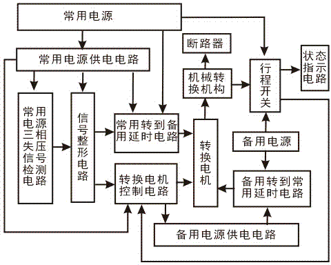
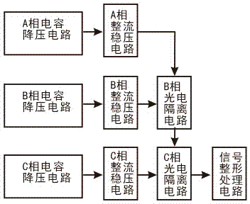
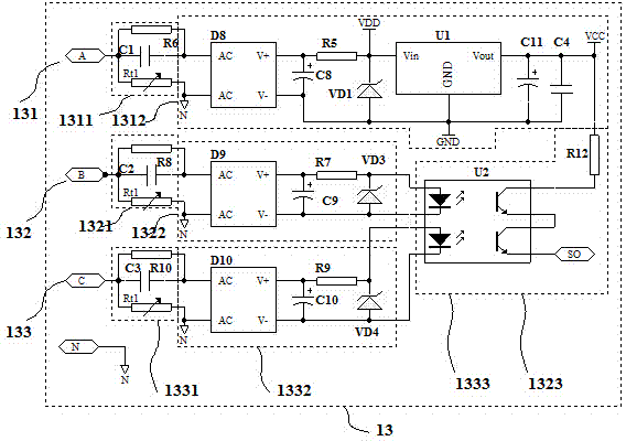
[0028] see figure 1 ~ Figure 5 , the control circuit of the simple dual power conversion device includes a conversion motor 11 and a travel switch 12 located in the mechanical conversion mechanism of the dual power conversion device, a common power supply three-phase voltage loss detection circuit 13, a signal shaping circuit 14, and a conversion motor control circuit 15, commonly used and forward to standby delay circuit 16, the common power supply circuit 17 for four circuit power supply, standby forward to common delay circuit 18, standby power supply circuit 19 for standby forward to commonly used delay circuit 18 power supply; Wherein , Commonly transferred to standby delay circuit 16, standby transferred to commonly used delay circuit 18 is provided with at least one group of controllabl...


PUM


Abstract

The invention discloses a control circuit of a simple double-power-supply changeover device. The control circuit is characterized in that when a frequently-used power supply is normal, a power supplying circuit of a reserve power supply is deenergized and does not work; an N phase of the frequently-used power supply and an N phase of the reserve power supply cannot be communicated at any time, so that the misoperation of a frontend residual current circuit-breaker caused by a current current-direction imbalance phenomenon resulting from the connection of voltage of two channels is avoided. A three-phase voltage loss detection circuit of the frequently-used power supply adopts a capacitive step-down circuit to replace a transformer, wherein a phase A voltage loss detection circuit of the frequently-used power supply is doubled as a power supplying circuit of the frequently-used power supply, and a gate circuit and a timer 555 integrated circuit are adopted as a logic control circuit instead of a microcontroller. The control circuit mainly has the following advantages that the whole circuit is simple, scientific and ingenious in structure, high in reliability, good in EMC (Electro-Magnetic Compatibility) and low in power consumption; the economical efficiency is high, the cost performance is high, the manufacturing is easy, the maintenance is convenient, the maintenance cost is low, and the control circuit is energy-saving and environment-friendly, thereby having relatively great popularization value.

Description

technical field [0001] The invention relates to the field of dual-power conversion switching appliances, in particular to an electronic control circuit for dual-power conversion switching appliances. Background technique [0002] In some important occasions of low-voltage power distribution, in order to reduce economic losses caused by power outages, two power sources are used for power supply: common use, backup or mutual backup. Power the diesel generator. When one power supply fails to supply power normally due to a fault during the power supply process, the device whose load can be switched to another power supply is called a dual power supply switching device, or TSE for short. It is intended to be called a dual power conversion device, and its load is automatically switched to The other power supply device is called automatic transfer switching equipment, or ATSE for short. [0003] At present, ATSE is generally composed of two parts: the automatic transfer switch bo...

Claims


Application Information

Patent Timeline
Patent Type & Authority Applications(China)
IPC IPC(8): H02J9/06
CPCY02B70/30Y04S20/20
Inventor 张焕明
Owner FOSHAN UNIVERSITY
Why Eureka
Eureka Blog
Learn More