Photometric system

A photometric system and a technology for measuring light sources, applied in the field of photometric systems, can solve the problems of measurement result error, complicated operation, etc., and achieve the effect of improving the accuracy rate

Inactive Publication Date: 2015-06-03
BEIJING HUIRONG GUANGCE TECH
View PDF7 Cites 2 Cited by
  • Summary
  • Abstract
  • Description
  • Claims
  • Application Information

AI Technical Summary

Problems solved by technology

[0004] The purpose of the present invention is to provide a photometry system to solve the technical problems that the existing light intensity measurement method needs to be measured separately by a photometer and a rangefinder, resulting in large errors in measurement results and cumbersome operations. The invented light metering system can take data in pairs synchronously during measurement, so as to measure illuminance data and distance data synchronously, and obtain accurate light intensity data through calculation

Method used


Image

  • Photometric system
  • Photometric system

Examples


Embodiment Construction

[0014] A light metering system according to the present invention will be described in detail below with reference to the drawings and embodiments.

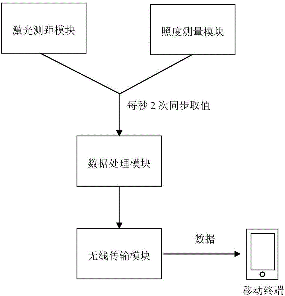
[0015] Such as figure 1 As shown, a photometric system of the present invention includes: a laser distance measuring module, an illumination measurement module and a data processing module; the laser distance measuring module is used to measure the distance between the light source and the position of the system, and will generate The distance data is transmitted to the data processing module; the illuminance measurement module is used to measure the illuminance at the position where the light generated by the light source propagates to the system, and transmits the generated illuminance data to the data processing module; the data processing module is used for Calculate the received distance data and illuminance data to obtain the light intensity data at the location of the system.

[0016] A light metering system based on the ...


PUM


Abstract

The invention provides a photometric system. The photometric system comprises a laser ranging module, an illumination measuring module and a data processing module; the laser ranging module is used for measuring the distance between a light source and the system and transmitting the generated distance data to the data processing module; the illumination measuring module is used for measuring the illumination of light generated by the light source and transmitted to the system and transmitting the generated illumination data to the data processing module; the data processing module is used for calculating the received distance data and illumination data to obtain the illumination intensity data of the position of the system. The laser ranging module and the illumination measuring module measure the distance and illumination synchronously, so that the illumination data and the distance data can be obtained at the same time and at the same place to the maximum, the accuracy rate for measuring data and the working efficiency can be improved, and the inconvenience of switching the devices manually is avoided while a photometer and a diastimeter are sequentially adopted for measuring.

Description

technical field [0001] The invention relates to the technical field of photometry, in particular to a photometry system. Background technique [0002] At present, the existing light intensity measurement method is to measure light intensity with a photometer and a rangefinder separately, so as to obtain standardized light intensity data. Specifically, after measuring the light intensity data emitted by a single light source, measure the distance with a distance meter at the same position where the light intensity data is measured, and finally use the two data to calculate on the calculator to get the final result. [0003] However, the above-mentioned method of measuring light intensity has many disadvantages: first, hand-held measurement will inevitably have displacement errors when replacing measuring equipment, and the attenuation of light is more sensitive to distance changes, specifically, it is attenuated according to the square of the distance , therefore, the displa...

Claims


Application Information

Patent Timeline
Patent Type & Authority Applications(China)
IPC IPC(8): G01J1/00
Inventor 徐大力
Owner BEIJING HUIRONG GUANGCE TECH
Why Eureka
Try Eureka