Transmission pulley, method for producing such a pulley, and power transmission system comprising such a pulley

A power transmission and transmission belt technology, applied in the direction of belts/chains/gears, transmission devices, components with teeth, etc., can solve the problems of cost, price and complexity of the power transmission system of the belt with longitudinal grooves, and achieve firmness Effect of axially compact, strong pulleys

Inactive Publication Date: 2015-06-03
AB SKF
View PDF0 Cites 2 Cited by
  • Summary
  • Abstract
  • Description
  • Claims
  • Application Information

AI Technical Summary

Problems solved by technology

This is relatively complicated and increases the cost price of the power transmission system of the belt with longitudinal grooves

Method used


Image

  • Transmission pulley, method for producing such a pulley, and power transmission system comprising such a pulley
  • Transmission pulley, method for producing such a pulley, and power transmission system comprising such a pulley
  • Transmission pulley, method for producing such a pulley, and power transmission system comprising such a pulley

Examples


Embodiment Construction

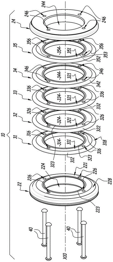
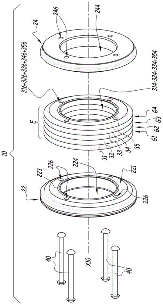
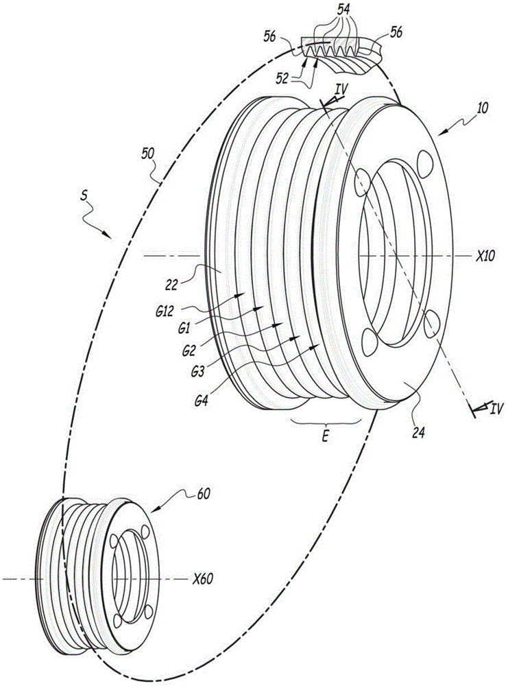
[0028] exist Figure 1 to Figure 4 The pulley 10 shown in is arranged to rotate about an axis of rotation X10, which is mounted on a support such as a flywheel, idler roller, or shaft (not shown). The pulley 10 comprises a first end cap 22 and a second end cap 24 , of annular shape, centered on the axis X10 in the mounted configuration of the pulley 10 , which define the ends of the pulley 10 along said axis X10. In other words, the end cap 22 constitutes the image 3 as well as Figure 4 The left side is along the first shaft end of the axis X10 of the pulley 10, while the end cover 24 is defined in image 3 as well as Figure 4 The second shaft end of the opposite pulley 10 on the right. Five crowns 31 , 32 , 33 , 34 , and 35 are arranged between said end caps 22 and 24 and along the direction of said axis X10 , which are identical to each other and each other from end cap 22 to end cap 24 are arranged in a continuous order along the axis X10.

[0029] The crown 31 co...


PUM


Abstract

A transmission pulley, for a power transmission system including a belt having longitudinal grooves, having at least one end cap, a stack (E) of identical crowns, as well as means of connecting the crowns and the cap, parallel to a rotational axis (X10) of the pulley and rotating about this axis. The cap defines a hollow housing wherein half of the adjacent crown is engaged on one side of a median plane of the crown.

Description

technical field [0001] The present invention relates to a drive pulley, and a power transmission system comprising a belt with longitudinal grooves and such a drive pulley. Finally, the invention relates to a method of manufacturing such a pulley. Background technique [0002] In the field of certain automotive engines, it is known to use a belt-based power transmission system with a belt on a drive pulley around a flywheel, idler rollers, or around a shaft that may drive a compressor, alternator, or possibly a crankshaft Or an equivalent material mounted for free rotation. In order to increase the maximum transmitted power between the pulley and the belt circulating around the pulley, it is known to use a belt with longitudinal grooves, usually with a V-shaped cross-section, while the belt itself has an elevation to fill these longitudinal grooves, in practice, It also defines a groove for accommodating the longitudinal elevation of the belt. [0003] Depending on the po...

Claims


Application Information

Patent Timeline
Patent Type & Authority Applications(China)
IPC IPC(8): F16H55/42
CPCF16H55/42B23P15/14F02B67/06F16H7/023F16H55/49Y10T29/49456
Inventor C.钱邦尼奥S.维奥尔特
Owner AB SKF
Why Eureka
Try Eureka