
Gear and method for producing same

A manufacturing method and technology of gears, applied in the directions of belts/chains/gears, gear teeth, components with teeth, etc., can solve problems such as stress increase and damage, and achieve the effect of improving long-term durability characteristics

Active Publication Date: 2015-05-27
ENPLAS CORP
View PDF9 Cites 5 Cited by
  • Summary
  • Abstract
  • Description
  • Claims
  • Application Information

AI Technical Summary

Problems solved by technology

In this kind of gear, when meshing with the teeth of the other gear, stress tends to concentrate on the concave point of the bottom of the tooth, and the stress may increase and cause damage.

Method used


Image

  • Gear and method for producing same
  • Gear and method for producing same
  • Gear and method for producing same

Examples


Embodiment Construction

[0053] Embodiments of the present invention will be described below with reference to the accompanying drawings.

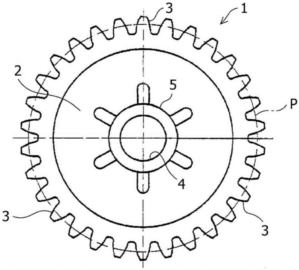
[0054] figure 1 It is a front view showing the overall shape of the gear of the present invention. The gear has a plurality of teeth and transmits rotational motion between the two shafts by meshing with the teeth of the counterpart gear. For example, it is widely used in power transmission mechanisms of automobiles, precision machinery, industrial machinery and their parts.

[0055] exist figure 1 In the gear 1, a plurality of teeth 3, 3... are formed on the outer peripheral side of the substantially disc-shaped web 2, and a boss 5 is formed at the center of the web 2. The shaft hole 4 where the shaft is fixed transmits the rotary motion between the two shafts. In addition, symbol P represents the pitch circle of the gear 1 .

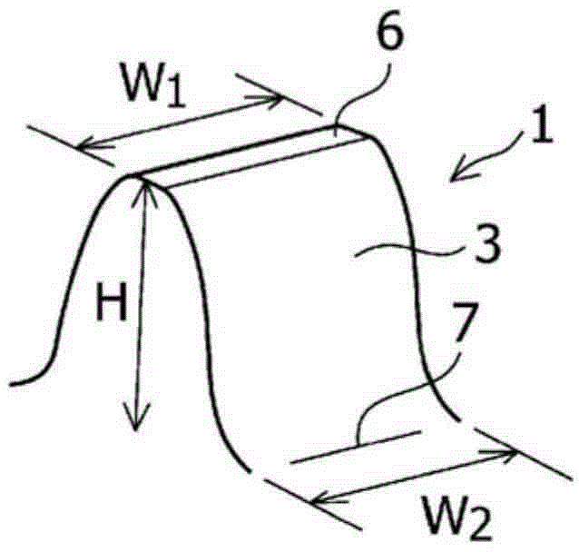
[0056] generally as figure 2 As shown, the tooth 3 of the gear 1 is formed as a tooth shape of a standard gear having a tooth surfa...


PUM

PropertyMeasurementUnit
widthaaaaaaaaaa

Abstract

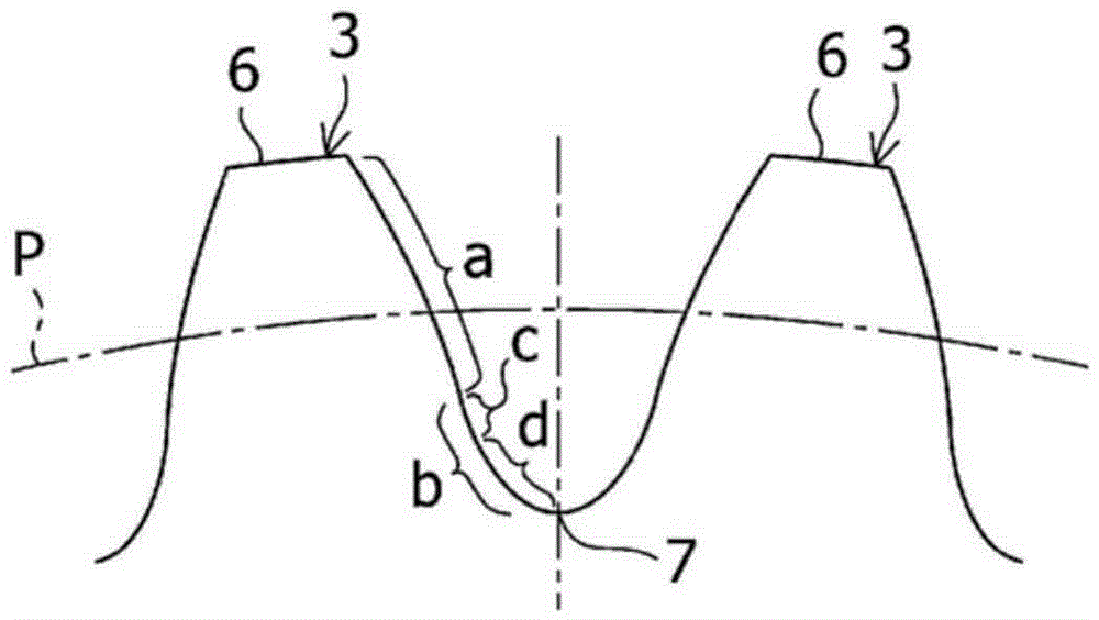
The present invention is a gear provided with a plurality of teeth (3), the gear transmitting rotational motion by meshing with teeth of a mating gear, wherein the shape (b) toward the root of each of the teeth (3) includes: a first curved surface (c) that is smoothly connected to a tooth surface (a) on an involute curve, the first curved surface (c) being represented by a curve that is inversely convex with respect to the tooth surface (a) on the involute curve; and a second curved surface (d) that is smoothly connected to the first curved surface (c) and is defined by a hyperbolic function that is convex in the same direction with respect to the first curved surface (c). It is thereby possible to reduce the tooth-root-side stress generated during meshing with the teeth of the mating gear, and to increase the strength of the teeth.

Description

technical field [0001] The present invention relates to a gear having a plurality of teeth that transmits rotational motion between two shafts by meshing with teeth of a counterpart gear. A gear with a tooth shape capable of generating stress and achieving high strength of the teeth and a method for manufacturing the same. Background technique [0002] Conventionally, gears used in power transmission mechanisms such as automobiles and precision machinery have been designed with various designs for increasing tooth strength. [0003] As such a gear, in a disc gear having teeth and tooth grooves, that is, a gear in the form of engagement between the teeth and the counterpart gear (pinion) interlocked through the tooth surface, there is such a structure that the tooth surface is at the end of the pinion. After the snap-in point, from the top of the tooth to the bottom of the tooth, the reference tooth surface is drawn by the pinion, which is close to the trochoid projected on ...

Claims


Application Information

Patent Timeline
Patent Type & Authority Applications(China)
IPC IPC(8): F16H55/08
CPCF16H55/0806B23F5/26Y10T409/105883Y10T74/19949
Inventor 近江宪仕
Owner ENPLAS CORP
Learn More