
Multi-wire sawing machine spindle system

A multi-wire cutting machine and spindle technology, used in fine working devices, stone processing equipment, manufacturing tools, etc., can solve problems affecting equipment stability, affecting the service life of spindle bearings, etc., to improve service life and prolong service life. , the effect of reducing heat

Inactive Publication Date: 2015-05-27
YANTAI LIKAI ELECTRONICS TECH
View PDF8 Cites 2 Cited by
  • Summary
  • Abstract
  • Description
  • Claims
  • Application Information

AI Technical Summary

Problems solved by technology

[0002] Multi-wire cutting is a new cutting method that brings abrasives into the semiconductor processing area for grinding through high-speed reciprocating motion of metal wires, and cuts hard and brittle materials such as semiconductors into hundreds of thin slices at a time. The key parts of the cutting machine drive the high-speed reciprocating motion of the metal wire. There are bearings at the supports of the main shaft and various parts, so the main shaft will generate a lot of heat during the high-speed reciprocating motion. If the heat is not controlled, it will affect the main shaft. The service life of the part bearings also affects the stability of the equipment. Therefore, a new technical solution is needed to solve the above technical problems

Method used


Image

  • Multi-wire sawing machine spindle system

Examples


Embodiment Construction

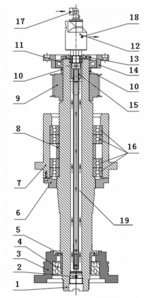
[0010] Referring to the accompanying drawings, a main shaft system of a multi-wire cutting machine is provided with a front end bearing 4 at the front end of the main shaft 1, a front end bushing 5 is provided between the front end bearing 4 and the main shaft 1, and the outer ring of the front end bearing 4 is installed on the front bearing seat 3 Above, there are two sets of main bearings 16 in the middle of the main shaft 1, the two sets of main bearings 16 are separated by an inner bushing 8, the outer ring of the main bearing 16 is installed on the main board bearing seat 7, and the front end of the main bearing 16 is pressed by the gland 6 , the rear of the main shaft 1 is provided with a synchronous pulley 9 and a rear bearing 11, a rear spacer 10 is provided between the rear end bearing 11 and the synchronous pulley 9, a rear cover 13 is installed on the rear end of the main shaft 1, and the outer ring of the rear end bearing 11 Installed on the rear bearing seat 14, th...


PUM


Abstract

The invention relates to a multi-wire cutter, in particular to a multi-wire sawing machine spindle system used for cooling circulating. The multi-wire sawing machine spindle system is characterized in that a front bearing is arranged at the front end of a spindle, a front bush is arranged between the front bearing and spindle, the outer circle of the front bearing is arranged on a front bearing pedestal, two groups of main bearings are arranged at the middle of the spindle, the two groups of main bearings are divided by an inner bush, the outer circles of the main bearings are arranged on a main board bearing pedestal, the front end is pressed by a pressure cover, the rear part is provided with a synchronous belt wheel and a rear bearing, a rear spacer bush is arranged between the rear bearing and synchronous belt wheel, a rear cover is arranged at the rear head face of the spindle, the outer circle of a rear bearing is arranged on a rear bearing pedestal, an oil pipe plug is arranged at the front end of the spindle, and an oil cooling pipe and a rotary joint are arranged at the rear end. Through improving the structure of the multi-wire sawing machine spindle part, the heat value of the spindle is effectively reduced, the service life of each bearing of the spindle is prolonged, and the equipment stability is improved.

Description

technical field [0001] The invention relates to a multi-wire cutting machine, in particular to a multi-wire cutting machine spindle system for cooling cycle. Background technique [0002] Multi-wire cutting is a new cutting method that brings abrasives into the semiconductor processing area for grinding through high-speed reciprocating motion of metal wires, and cuts hard and brittle materials such as semiconductors into hundreds of thin slices at a time. The key parts of the cutting machine drive the high-speed reciprocating motion of the metal wire. There are bearings at the supports of the main shaft and various parts, so the main shaft will generate a lot of heat during the high-speed reciprocating motion. If the heat is not controlled, it will affect the main shaft. The service life of the part bearings also affects the stability of the equipment. Therefore, a new technical solution is needed to solve the above technical problems. Contents of the invention [0003] I...

Claims


Application Information

Patent Timeline
Patent Type & Authority Applications(China)
IPC IPC(8): B28D5/04
CPCB28D5/045
Inventor 吕春哲孙旭东
Owner YANTAI LIKAI ELECTRONICS TECH
Learn More