
Panoramic video stitching method and device

A panoramic video and splicing device technology, which is applied in the field of image processing, can solve the problems of high cost, single picture, and does not support irregular picture splicing, etc., and achieve the effect of reducing performance requirements, flexible solutions, and improving panoramic splicing capabilities

Active Publication Date: 2015-05-20
ZHEJIANG UNIVIEW TECH CO LTD
View PDF7 Cites 22 Cited by
  • Summary
  • Abstract
  • Description
  • Claims
  • Application Information

AI Technical Summary

Problems solved by technology

[0005] However, the first solution relies heavily on the mechanical structure of the front-end equipment, and has relatively high requirements for the installation of the front-end equipment. At the same time, the picture after splicing is relatively single, and it is generally only suitable for the splicing effect of two front-end equipment.
The second solution needs to convert the pixels of the video screen captured by each front-end device because of the splicing pixel conversion matrix. After decoding, the look-up table conversion of pixel points consumes more computer performance. Generally, a splicing server with relatively strong performance is required to complete the panorama. video splicing
And the complexity of the stitching algorithm will increase sharply with the increase of stitching front-end equipment, and there are relatively strict requirements for the presentation mode of the video images after panoramic stitching, generally does not support the stitching of irregular images, such as the panorama stitching of pin-shaped images
At the same time, due to splicing on the client side, when the performance is insufficient, load balancing cannot be performed, and a server with better performance must be used instead. The requirements for splicing servers are high and the cost is relatively high.

Method used


Image

  • Panoramic video stitching method and device
  • Panoramic video stitching method and device
  • Panoramic video stitching method and device

Examples


Embodiment 1

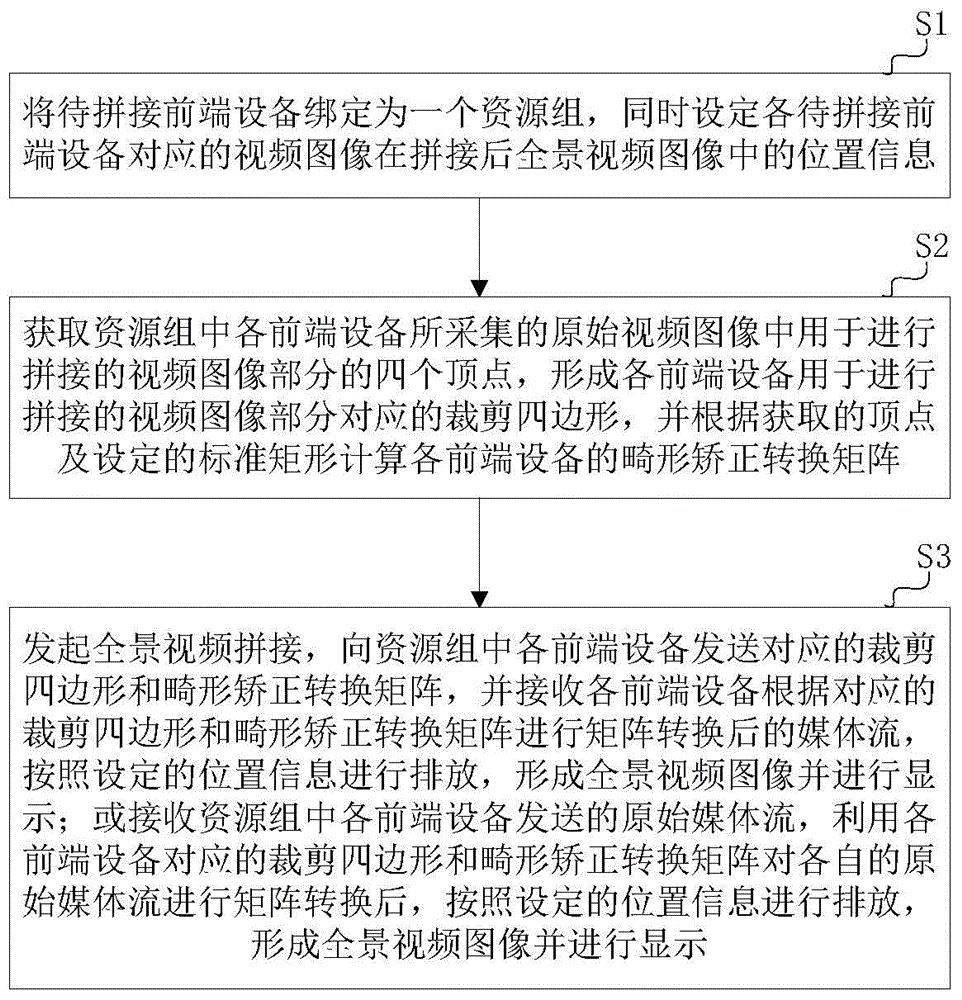
[0048] Embodiment 1. In the method of manually correcting each front-end device, an appropriate point is manually selected in the original video image collected by it according to the reference object. For example, on the client side, four vertices corresponding to the video images to be spliced ​​are selected from the original video images collected by each front-end device according to manual comparison.

Embodiment 2

[0049] Embodiment 2, using the method of corner point comparison, that is, the corner points in the respective video images are first obtained by the corner point detection algorithm, and then the corner points of the original video images collected by two adjacent front-end devices with position information are compared to obtain The corner point information shared by the overlapping parts of the video images of the two front-end devices is common, and the corner points closest to the two ends of the overlapping part are selected from the corner point information in common as the two vertices of the video image part for splicing; for only For a video image collected by a front-end device adjacent to other front-end devices on one side, two corresponding vertices are selected on the other side of the video image according to the two selected vertices adjacent to other front-end devices.

[0050] Since the original video images collected by two adjacent front-end devices have th...

Embodiment 3

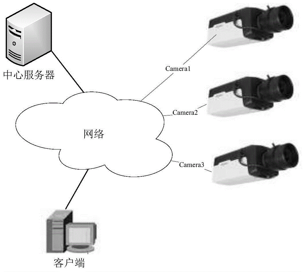
[0061] Embodiment 3, matrix conversion is performed in the front-end equipment in a distributed manner. That is, after the panoramic video splicing is initiated, the cropping quadrilateral and distortion correction transformation matrix of each front-end device in the resource group are sent to the corresponding front-end device, and the front-end device performs cropping and matrix conversion respectively. The clipping quadrilateral and deformity correction transformation matrix of each front-end device can be directly sent to each front-end device by the client, or the client notifies the central server to send it to each front-end device. The present invention is not limited to each front-end device obtaining its own clipping quadrilateral and deformity The way to rectify the transformation matrix. The media stream sent by the front-end device is the converted video image. After the client receives and decodes it, it directly discharges it according to the set position info...


PUM


Abstract

The invention discloses a panoramic video stitching method and device. The panoramic video stitching method is used for stitching video images acquired by front-end devices to be stitched into a panoramic video image through a client and comprises the steps of binding the front-end devices to be stitched into a resource group, acquiring four vertices of a stitched video image part of each front-end device so as to form a cut quadrilateral corresponding to each corresponding front-end device, calculating the deformity correction and conversion matrix of each front-end device according to the acquired vertices and a set standard rectangle, converting the video images acquired by all the front-end devices, and then, laying out the converted video images according to set position information, so as to form and display a panoramic video image. The panoramic video stitching device disclosed by the invention comprises a configuration module, a vertex acquisition and matrix generation module and a stitching module. According to the method and the device, disclosed by the invention, the deformity correction and conversion can be carried out by the front-end devices or the client so as to realize panoramic stitching, and the requirements on the performance of matrix conversion equipment are not high, so that the method and the device are particularly applicable to the upgrade and development of old items.

Description

technical field [0001] The invention belongs to the technical field of image processing, and in particular relates to a panoramic video splicing method and device in video surveillance. Background technique [0002] With the development of video surveillance, customers have higher and higher requirements for the viewing angle and visual range of surveillance video. Promote the gradual emergence and popularity of panoramic video stitching, but limited by the system framework and hardware performance, there are not many products on the market that can meet customer requirements, and the visual range of the stitched video is relatively limited by hardware performance, which affects the panorama Promotion and popularization of video stitching solutions. [0003] In video surveillance, multiple cameras are often used to monitor different angles of the same scene to obtain multiple video images of the same scene at different angles, and then the multiple video images are spliced ...

Claims


Application Information

Patent Timeline
IPC IPC(8): H04N7/18H04N5/265
Inventor 王江柱
Owner ZHEJIANG UNIVIEW TECH CO LTD
Learn More