Continuous circulation drilling technology suitable for gas-liquid two-phase flow drilling
A technology of gas-liquid two-phase flow and technology, which is applied in wellbore/well components, earthwork drilling, and flushing wellbore, etc. It can solve problems such as unstable buoyancy of the drill string, potential safety hazards, and large bottom-hole pressure fluctuations. Achieve the effects of increasing reliability and safety, improving drilling efficiency and reducing slug flow
- Summary
- Abstract
- Description
- Claims
- Application Information
AI Technical Summary
Problems solved by technology
Method used
Image
Examples
Embodiment 1
[0044] A continuous circulation drilling process suitable for gas-liquid two-phase flow drilling, including the connection process of ground equipment, the process of connecting a column or a single root, and the drilling process.
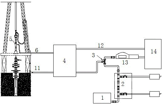
[0045]The connection process of the ground equipment is as follows: the ground equipment includes the gas injection unit 1, the safety pressure relief mechanism 2, the gas-liquid mixing device 3, and the gate valve control system 4, and the gas injection unit 1, the safety pressure relief mechanism 2, the gas Liquid mixing device 3 and gate valve control system 4; gate valve control system 4 is connected to the riser through the main circulation channel 11, connected to the drill floor through the side circulation channel 6 for standby, and connected to the circulation tank 14 through the pressure relief channel 12;
[0046] The connecting column or single process is as follows:
[0047] a. After drilling to the bottom, connect the first circulatio...
Embodiment 2
[0066] A continuous circulation drilling process suitable for gas-liquid two-phase flow drilling, including:
[0067] The connection process of ground equipment is as follows: ground equipment includes gas injection unit, safety pressure relief mechanism, gas-liquid mixing device, and gate valve control system. During operation, the gas injection unit, safety pressure relief mechanism, gas-liquid mixing device, and gate valve system are connected in sequence. Then connect the main circulation channel from the gate valve control system to the standpipe, the side circulation channel with pressure gauge to the drill floor for backup, and the pressure relief channel to the circulation tank.
[0068] The process of connecting uprights (single) is as follows:
[0069] a. After drilling to the bottom, connect the first circulation guide nipple to the top of the last drill pipe, the main circulation channel is connected, the gas-liquid two-phase flow enters the standpipe through the m...
Embodiment 3
[0089] This embodiment describes the circulation guide pup joint used in the present invention.
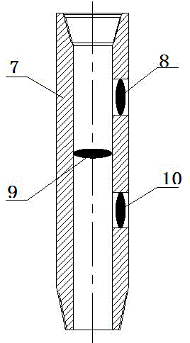
[0090] The circulation guide pup joint includes: main valve, side valve, and pressure relief valve. The main valve is set in the pup joint body, and the side valve is set on the side wall of the pup joint body below the main valve to connect to the circulation pipeline. The pressure relief valve is arranged on the side wall of the sub body above the main valve, and the main valve is located in the sub body between the side valve and the pressure relief valve. The main valve is set at the center of the sub body and is coaxial with the sub body. The diameter of the relief valve is smaller than that of the side valve. The circulation steering sub-joint is connected between the drill pipes and goes into the well with the drilling tool during drilling.
[0091] In the process of gas drilling or gas-liquid mixed phase drilling, the circulation guide sub is connected to the single root...
PUM
 Abstract
Description
Claims
Application Information
 - R&D Engineer
- R&D Manager
- IP Professional
- Industry Leading Data Capabilities
- Powerful AI technology
- Patent DNA Extraction
Browse by: Latest US Patents, China's latest patents, Technical Efficacy Thesaurus, Application Domain, Technology Topic, Popular Technical Reports.
© 2024 PatSnap. All rights reserved.Legal|Privacy policy|Modern Slavery Act Transparency Statement|Sitemap|About US| Contact US: help@patsnap.com


