
Valve with valve closure body

A valve closing and closing body technology, which is applied in the valve field of piston pumps, can solve problems such as mechanical load, noise, and vibration of the valve closing body, and achieve the effects of reducing vibration, reducing pressure fluctuations, and low manufacturing costs

Inactive Publication Date: 2011-05-25
ROBERT BOSCH GMBH
View PDF9 Cites 11 Cited by
  • Summary
  • Abstract
  • Description
  • Claims
  • Application Information

AI Technical Summary

Problems solved by technology

These pressure fluctuations not only vibrate the valve closing body, but also cause significant noise and impose mechanical loads on the piston pump and the hydraulic components connected to it

Method used


Image

  • Valve with valve closure body
  • Valve with valve closure body
  • Valve with valve closure body

Examples


Embodiment Construction

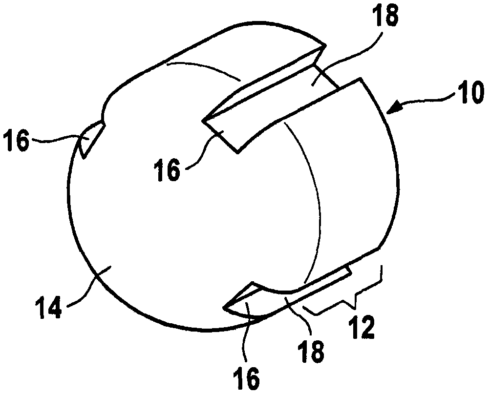
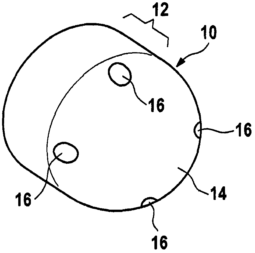
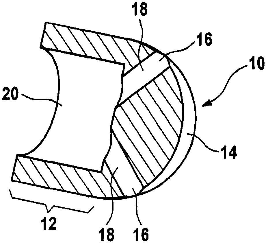
[0050] Figure 1 to Figure 3 Two embodiments of the valve closing body 10 are shown, which have a cylindrical guide section 12 and a hemispherical sealing section 14 facing the cylindrical guide section in the longitudinal direction. The sealing section 14 has a curved surface and four passage openings 16 arranged at regular intervals in the circumferential direction of the sealing section 14 .

[0051] exist figure 1 In the preferred embodiment, each of the channel openings 16 is terminated by a straightly extending channel 18 having a rectangular channel cross-section. The channel 18 is arranged on the outer longitudinal side of the cylindrical guide section 12 and is open towards the outside on the longitudinal side, ie it has only three defined rectangular channel walls.

[0052] exist figure 2 and image 3 In the exemplary embodiment, a valve closing body 10 is provided in which the guide section 12 has a hollow cylindrical interior 20 . The channel 18 is designed a...


PUM


Abstract

The invention relates to a valve for a piston pump, wherein the valve (22) comprises a valve closure body (10) and a valve seat (26) disposed longitudinally facing to the valve closure body (10); the valve closure body (10) comprises a cylindrical guide section (12) and a hemispheric sealing section (14) longitudinally facing to the cylindrical guide section (10) and facing to the valve seat (26); the sealing section is used for selectively closing and opening a hole (30) enclosed by the valve seat (26); according to the invention, the sealing section (14) comprises at least one channel opening (16) which is located out of the hole (30) enclosed by the valve seat (26) under the state that the valve (22) is closed, and extended into a channel (18) in the valve closure body (10) substantially extending along a flow direction.

Description

technical field [0001] The invention relates to a valve for a piston pump having a valve closing body and a valve seat arranged longitudinally opposite the valve closing body. The valve closing body has a cylindrical section and a hemispherical sealing section facing the cylindrical section in the longitudinal direction and facing the valve seat for selectively closing and opening the hole enclosed by the valve seat. Furthermore, the invention relates to a piston pump for a hydraulic or pneumatic system having such a valve and to the use of such a valve. Background technique [0002] In the prior art, valves are used in various ways in hydraulic systems, in particular in piston pumps of vehicle brake systems (DE 39 07 969 A1 and DE 10 2006 048 903 A1). In these braking systems, piston pumps not only control the pressure in the wheel cylinders, but are also used in anti-lock braking systems (ABS), for example, to return brake fluid from the wheel cylinders to the master cyli...

Claims


Application Information

Patent Timeline
Patent Type & Authority Applications(China)
IPC IPC(8): F04B53/10
CPCF16K15/026F04B53/1017F04B53/10F16K15/02F16K15/025F16K27/0209F16K31/122
Inventor O·格特纳O·亨尼希
Owner ROBERT BOSCH GMBH
Learn More