A high-temperature gas-solid filtration separation process

A technology of filtration and separation, high temperature gas, applied in separation methods, dispersed particle separation, dispersed particle filtration, etc., can solve the problems of hindering the falling of dust, insufficient dust removal efficiency, etc., to prevent dust agglomeration, reduce equipment maintenance costs, and reduce equipment. Effects of maintenance and upkeep costs

Active Publication Date: 2016-06-08
BEIJING EDGEIN TECH +1
View PDF7 Cites 0 Cited by
  • Summary
  • Abstract
  • Description
  • Claims
  • Application Information

AI Technical Summary

Problems solved by technology

[0005] For this reason, the first technical problem to be solved by the present invention is that in the prior art, the direction of the process airflow used for gas-solid separation of high-temperature dust-laden gas is opposite to the falling direction of dust, which hinders the falling of dust and leads to insufficient dust removal efficiency;

Method used


Image

  • A high-temperature gas-solid filtration separation process
  • A high-temperature gas-solid filtration separation process

Examples


Embodiment 1

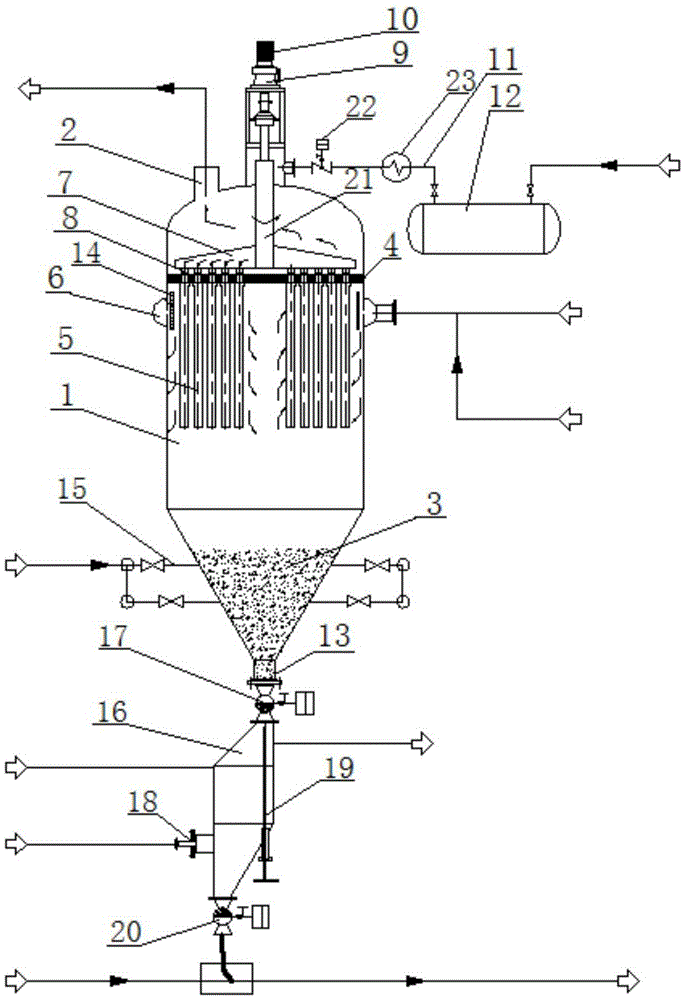
[0043] This embodiment provides a high-temperature dust-containing gas separation process used in the production of melamine. In the melamine production device, the temperature of the reaction product gas from the catalytic reactor is about 400 ° C. The gas contains catalyst particles and by-product dust, and also contains Flammable and toxic ammonia gas.

[0044] The separation process of the high-temperature dust-laden gas comprises the following steps:

[0045] S1. The high-temperature dust-laden gas enters the feed ring pipe 6 from the inlet of the feed ring pipe 6, and then enters the filter body 1 through the air inlet hole on the filter body 1 and passes through the ring baffle plate 14 and the filter body. The gap on the inner wall of the body 1 enters the inner cavity of the filter body 1;

[0046] S2. The high-temperature dust-laden gas enters the upper cavity of the filter body 1 after being filtered through a metal punching tube covered with glass fiber cloth, and...

Embodiment 2

[0059] This example provides a high-temperature dust-containing gas separation process used in the methanol-to-gasoline fluidized-bed process. In the methanol-to-gasoline fluidized-bed process, the reaction product gas from the catalytic reactor has a temperature of about 380°C, which is alkanes and olefins. , aromatic hydrocarbons and other explosive gases, which contain catalyst dust particles, and there are carbon deposits and coking on the surface and interior of the catalyst particles.

[0060] The separation process of the high-temperature dust-laden gas comprises the following steps:

[0061] S1. The high-temperature dust-containing gas enters the feed ring pipe 6 from the inlet of the feed ring pipe 6, enters the filter body 1 through the air inlet hole arranged on the filter body 1, and passes between the annular baffle plate 14 and the filter body 1. The gap enters the inner cavity of the filter body 1;

[0062] S2. The high-temperature dust-laden gas entering the i...


PUM

PropertyMeasurementUnit
lengthaaaaaaaaaa
diameteraaaaaaaaaa
particle diameteraaaaaaaaaa

Abstract

The invention discloses a separation process of a high-temperature dusty gas. The separation process comprises the following steps: S1, introducing the high-temperature dusty gas from an annular feed pipe (6) into a filter body (1); S2, filtering through a filter pipe coated with a filter medium, and then discharging through a clean gas outlet (2), wherein a small part of dust is accumulated on the surface of the filter medium; S3, introducing a chemical cleaning gas to resolve the dust on the filter medium; S4, introducing a back-blowing gas into a back-blowing arm (7), and blowing into the filter pipe (5) so that the dust on the filter pipe (5) and the surface of the filter medium is desquamated; S5, introducing flexible gas into a flexible gas input device (15), fully filling a displacement gas into a dust discharge buffer tank (16), and opening a dust discharge valve (17) to discharge the dust into the dust discharge buffer tank (16); S6, opening an automatic control dust discharge valve (20) to deliver the dust into a next procedure. The separation process disclosed by the invention can be used for improving the gas-solid separation efficiency, prolonging the service life of the filter pipe (5) and reducing the installation and maintenance cost of the device and is especially suitable for being used as large-sized gas-solid separation equipment.

Description

technical field [0001] The invention relates to a filtration process, in particular to a filtration separation process for gas-solid separation of high-temperature dust-laden gas. Background technique [0002] Gas-solid filtration and separation refers to the method of separating and purifying mixed gases containing dispersed or condensed solids. It is an important chemical unit operation. have a wide range of applications. [0003] At present, there are many gas-solid separation methods in the industry to filter and separate dusty gases to purify industrial gases or recycle valuable resources, mainly including: gravity settling method, the gravity settling device has simple structure and low cost, but The gas velocity is low, the equipment is huge, and only coarse particles above 100 μm can be separated; the washing separation method has a small equipment footprint, low investment, and is suitable for treating gases containing harmful substances, but this method requires w...

Claims


Application Information

Patent Timeline
Patent Type & Authority Patents(China)
IPC IPC(8): B01D46/00B01D46/30B01D46/42
Inventor 唐印孔德利刘朝慧
Owner BEIJING EDGEIN TECH
Why Eureka
Try Eureka