
Novel quenching ring for entrained-bed gasifier

A fluidized bed gasifier and chilling ring technology, which is applied in the mechanical details of gasification units, the manufacture of combustible gases, and the petroleum industry, can solve the problems of reduced life, high temperature, and difficulty in manufacturing and assembly, and can reduce manufacturing costs and costs. The effect of processing cost, high material utilization rate and reduction of spare parts cost

Inactive Publication Date: 2015-05-13
中国东方电气集团有限公司
View PDF3 Cites 5 Cited by
  • Summary
  • Abstract
  • Description
  • Claims
  • Application Information

AI Technical Summary

Problems solved by technology

[0007] Aiming at the defects and deficiencies of the quenching ring in the prior art, the present invention provides a novel quenching ring for a fluidized bed gasification furnace, which overcomes the problem that the existing quenching ring directly contacts with high-temperature syngas and molten slag when working. The defect caused by its high temperature and reduced service life due to direct erosion greatly improves the anti-deformation, wear-resistant, and anti-erosion capabilities of the chilled ring to the fire surface
It overcomes the defects of deformation and burn-through of the downcomer due to the uneven distribution of water film and flow interruption, and also overcomes the defects of the quenching ring in the prior art that are difficult to manufacture and assemble

Method used


Image

  • Novel quenching ring for entrained-bed gasifier
  • Novel quenching ring for entrained-bed gasifier

Examples


Embodiment Construction

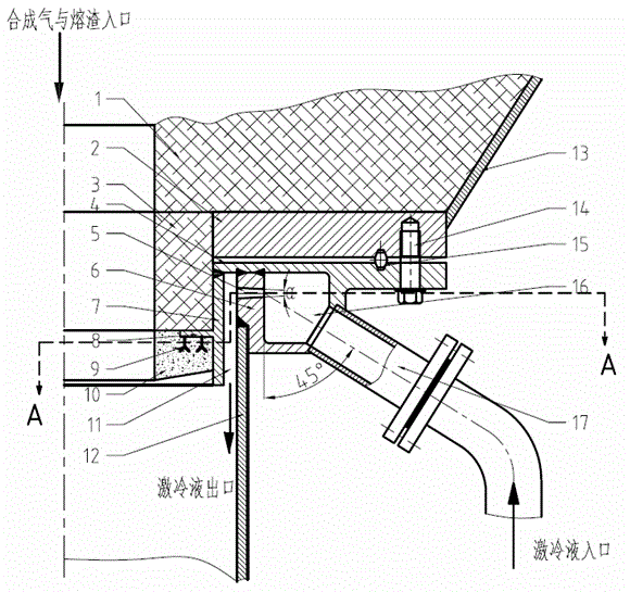
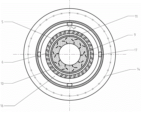
[0028] Below in conjunction with accompanying drawing and specific embodiment the present invention is described in further detail:

[0029] like Figure 1-2 As shown, a novel fluidized bed gasification furnace quenching ring of the present invention includes an annular outer ring plate 4, an annular inner ring plate 7, an annular spacer ring 6, a downcomer 12, a quenching liquid delivery pipe 17, and an annular The outer ring plate 4 comprises a horizontal annulus and a longitudinal annulus below the horizontal annulus. The annular inner ring plate 7 and the annular spacer ring 6 are all fixed on the inner side of the horizontal annulus of the annular outer ring plate 4. The spacer ring 6 is located between the annular inner ring plate 7 and the longitudinal ring surface 1 of the annular outer ring plate, and the downcomer 12 is installed at the lower end of the annular spacer ring 6; A quenching liquid distribution chamber 16 is formed between the ring surfaces, and the que...


PUM


Abstract

The invention discloses a novel quenching ring for an entrained-bed gasifier. The quenching ring comprises an annular outer ring plate, an annular inner ring plate, an annular retainer and a descending pipe, wherein the annular outer ring plate comprises a horizontal ring face I and a longitudinal ring face I which is located on a lower face of the horizontal face I; the annular inner ring plate and the annular retainer are fixedly arranged inside the lower face of the horizontal ring face I, the annular retainer is located between the annular inner ring plate and the longitudinal ring face I, and the descending pipe is mounted at the lower end of the annular retainer; quenching liquid distribution chambers are formed between the annular retainer and the horizontal ring face I and between the annular retainer and the longitudinal ring face I and are connected with a quenching liquid conveyer; annular protective layers are arranged on fire-facing faces of the annular outer ring plate and the annular inner ring plate. According to the novel quenching ring disclosed by the invention, the fire facing face of the quenching ring is prevented from being directly brushed by high-temperature synthetic gas and cinders to be damaged, and the working temperature of the fire facing face of the quenching ring can be further greatly reduced, the service life of the quenching ring is prolonged, and the slagging outlet can be further prevented from being blocked. The novel quenching ring disclosed by the invention is easy to produce and relatively low in manufacturing and processing costs.

Description

technical field [0001] The invention relates to a quenching device in a coal-water slurry or pulverized coal pressurized entrained-flow gasification furnace, in particular to a novel quenching ring of the entrained-flow gasification furnace applied in the water quenching type. Background technique [0002] Coal gasification technology is a clean coal technology that utilizes coal efficiently and cleanly. The key equipment of coal water slurry or coal powder pressurized entrained entrained bed gasification technology is the gasifier, and coal powder or coal water slurry is in the gasifier The coal gasification reaction occurs in the gasification chamber, and the high-temperature crude synthesis gas of about 1200-1700 ° C and the molten slag enter the quenching chamber, where the high-temperature crude synthesis gas and slag are cooled and the gas slag is separated. The key component of the quenching chamber is the quenching ring. The function of the quenching ring is to...

Claims


Application Information

Patent Timeline
IPC IPC(8): C10J3/84C10J3/72
CPCC10J3/84C10J3/72C10J2200/09
Inventor 张春飞王晓亮王希李少华吴家桦胡春云
Owner 中国东方电气集团有限公司
Learn More