
LED (Light Emitting Diode) lamp with glass lampshade with internally-coated remote fluorescent powder and process

A technology of remote phosphor and glass lampshade, applied in the direction of lampshade, coating, light source, etc., can solve the problems of large consumption of phosphor, high mold cost, poor heat dissipation performance of lamps, etc., and achieves wide lighting range, simple design, The effect of improving the luminous efficiency

Inactive Publication Date: 2015-05-06
赵宁
View PDF5 Cites 2 Cited by
  • Summary
  • Abstract
  • Description
  • Claims
  • Application Information

AI Technical Summary

Problems solved by technology

Due to the integrated injection molding, the phosphor consumption is large, the mold cost is high, and the heat dissipation performance of the lamp is not good

Method used


Image

  • LED (Light Emitting Diode) lamp with glass lampshade with internally-coated remote fluorescent powder and process
  • LED (Light Emitting Diode) lamp with glass lampshade with internally-coated remote fluorescent powder and process
  • LED (Light Emitting Diode) lamp with glass lampshade with internally-coated remote fluorescent powder and process

Examples


Embodiment 1

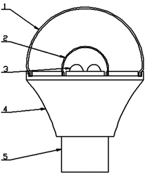
[0031] Please refer to figure 1 , an LED lamp using a glass lampshade coated with remote phosphor, which includes a lamp base 5, a radiator 4, and a light-emitting chip 3. One end of the radiator is connected to the lamp holder, and the light-emitting chip is installed on the other end of the radiator. In that: a glass lampshade 2 with phosphor powder is installed outside the luminescent chip, and the glass lampshade with phosphor powder is fixed on the other end of the radiator; in the installed state, the glass lampshade with phosphor powder is gas-tight and connects the light emitting chip and the The outside is isolated; the inner wall of the glass lampshade with fluorescent powder is coated with remote phosphor; the glass lampshade with fluorescent powder has an outer cover 1 installed in the slot at the other end of the radiator.

[0032] Certainly, in this implementation example, the outer cover may not be used at all, and the luminous performance will not be affected. ...

Embodiment 2

[0035] please see figure 2, an LED lamp using a glass lampshade coated with remote phosphor powder is basically the same as in Example 1, the difference is that: the glass lampshade with phosphor powder is semi-ellipsoidal, the upper part of the outer cover is a spherical part, and the lower part is Approximate cylindrical shape.

Embodiment 3

[0037] please see image 3 1. An LED lamp using a glass lampshade coated with remote phosphor powder is basically the same as that in Embodiment 1, except that the glass lampshade with phosphor powder is hemispherical, and the outer cover is hemispherical.


PUM

PropertyMeasurementUnit
diameteraaaaaaaaaa
heightaaaaaaaaaa
alcoholysis degreeaaaaaaaaaa

Abstract

The invention discloses an LED (Light Emitting Diode) lamp with a glass lampshade with internally-coated remote fluorescent powder and a process. The LED lamp comprises a lamp adapter, a heat dissipater and light emitting chips, wherein one end of the heat dissipater is connected with the lamp adapter, and the light emitting chips are mounted at the other end of the heat dissipater. The LED lamp is characterized in that the glass lampshade with fluorescent powder is mounted outside the light emitting chips and is fixedly arranged at the end, where the light emitting chips are mounted, of the heat dissipater; the internal wall of the glass lampshade with the fluorescent powder is coated with a remote fluorescent powder coating. The invention further discloses a method for coating the fluorescent powder coating. The LED lamp mainly has the following positive effects that the light penetration performance is good, and the light emitting efficiency is higher; the product design is simple, and the lighting range is wider; the consumption of the fluorescent powder is lower; the heat dissipating performance is better, and the LED lamp is safer.

Description

technical field [0001] The invention relates to the technical field of lighting equipment, in particular to an LED lamp using a glass lampshade coated with remote fluorescent powder and its technology. Background technique [0002] In the light source of traditional LED lights, phosphors are coated on the wafer, although it can achieve white light effect, but the luminous efficiency is low, the light is dazzling and the directionality is strong. With the development of power and integration of LED devices, a large amount of heat released by wafers leads to serious thermal quenching of phosphor materials, which leads to color shift of white LED light sources. [0003] Using LED remote phosphor, since there is a certain distance between the phosphor material and the wafer, the hot spots generated by the wafer have very little effect on the thermal attenuation of the phosphor. In addition, LED remote phosphor can be designed in any shape and angle, with uniform light and high ...

Claims


Application Information

Patent Timeline
Patent Type & Authority Applications(China)
IPC IPC(8): F21S2/00F21V3/04C09D5/22C09D129/04F21Y101/02
CPCC08K3/22C08K2003/2227C08K2201/003C09D5/22C09D7/61C09D129/04F21V3/12
Inventor 赵宁
Owner 赵宁
Learn More