
Water-cooled heat sink

A water-cooling heat dissipation and water-cooling technology, which is applied in the direction of cooling/ventilation/heating transformation, etc., can solve the problems of high material requirements for water-cooled pipes, difficult to process complex pipelines, and difficult maintenance and repair.

Inactive Publication Date: 2015-04-29
RAINTREE SCI INSTR SHANGHAI
View PDF5 Cites 0 Cited by
  • Summary
  • Abstract
  • Description
  • Claims
  • Application Information

AI Technical Summary

Problems solved by technology

[0004] 1. Use the casting method to cast the water-cooled metal pipe into the water-cooled shell. This method has high requirements on the material of the water-cooled pipe. Its melting point and metallographic thermal stability temperature must be much higher than the casting temperature of the shell, and when the pipeline is complex When the casting mold cost is too high, especially not suitable for small batch manufacturing
[0005] 2. The water-cooling channel is directly processed in the water-cooling shell, which requires high processing technology, and it is also difficult to process complex pipelines
[0006] 3. Double-plate structure, that is, the pipeline is processed on the hot plate and the cold plate, and then the two plates are connected. This structure has a large sealing area, and the sealing surface is often close to the heat source. The reliability is low, and maintenance and repair are often difficult
[0007] Production lines and equipment have relatively high requirements for the reliability and maintainability of these cooling systems, especially for water-cooling systems with large heat generation, the above-mentioned cooling systems are often difficult to achieve

Method used

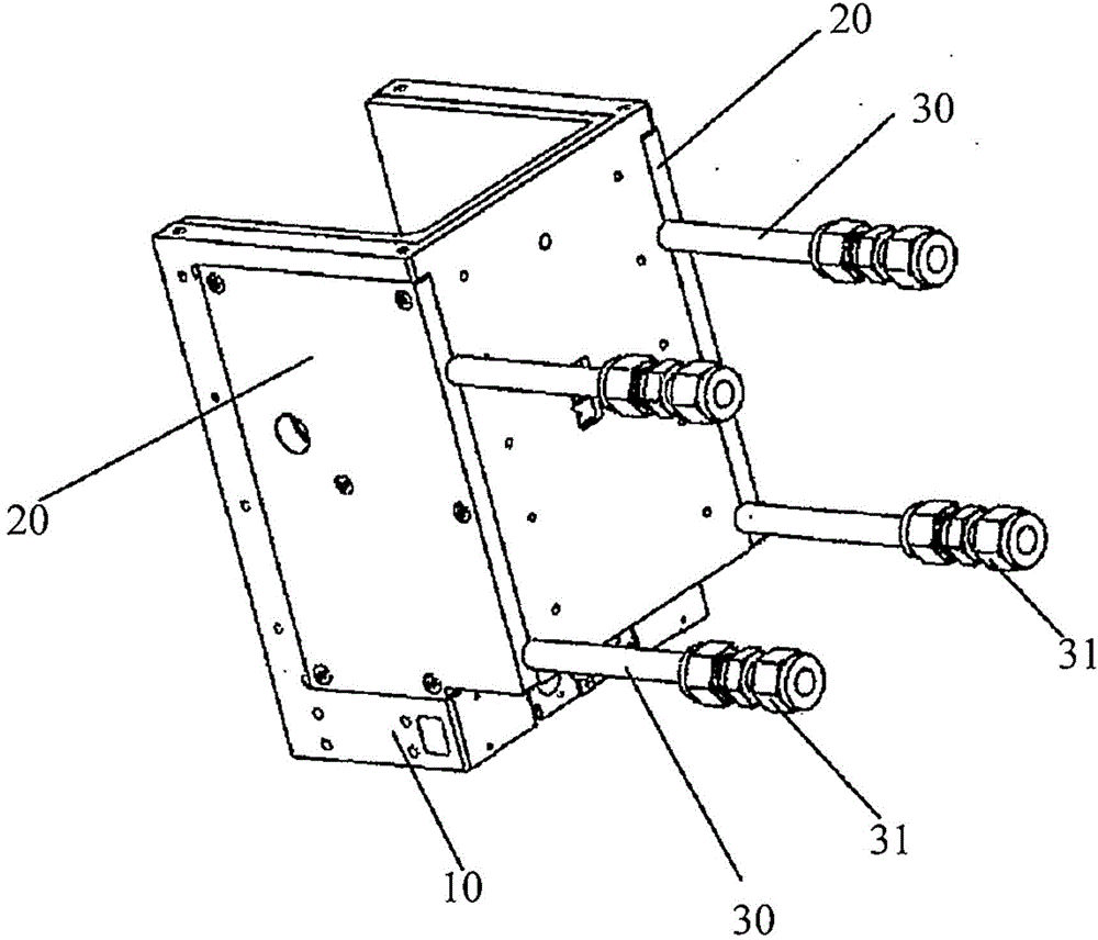
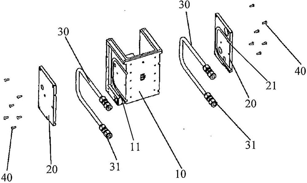
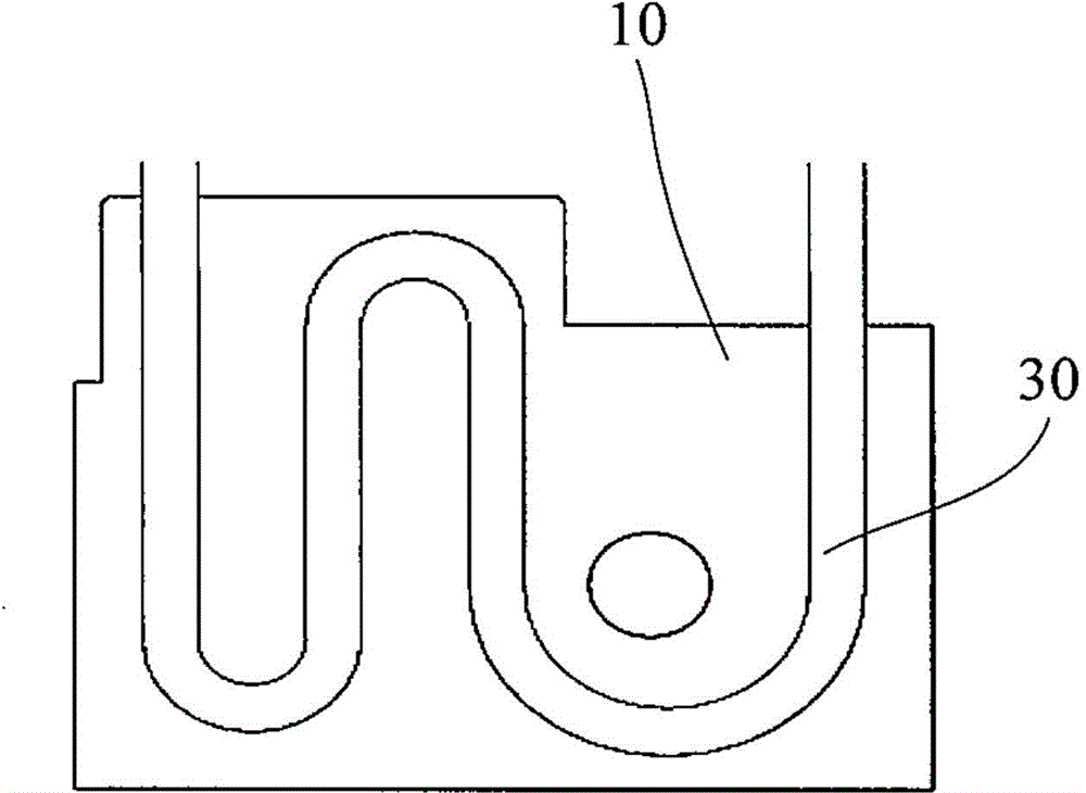

Image

  • Water-cooled heat sink
  • Water-cooled heat sink
  • Water-cooled heat sink

Examples


Embodiment Construction

[0030] In the following detailed description of the preferred embodiment, reference is made to the accompanying drawings which form a part hereof. The accompanying drawings show, by way of example, specific embodiments in which the invention can be practiced. The illustrated embodiments are not intended to be exhaustive of all embodiments in accordance with the invention. It is to be understood that other embodiments may be utilized and structural or logical changes may be made without departing from the scope of the present invention.

[0031] In the following specific descriptions, directional terms such as "left", "right", "top", "bottom", "front", "rear", "lead", "forward", "rear" etc. , used with reference to the directions described in the attached drawings. Components of embodiments of the present invention may be positioned in a variety of different orientations, and directional terms are used for purposes of illustration and not limitation.

[0032] figure 1 A per...


PUM


Abstract

The invention provides a water-cooled heat sink. The water-cooled heat sink comprises a water-cooling housing, splints and water-cooling pipes, wherein the water-cooling housing is used for accommodating an energy source, and an outer groove is formed in the outer side of at least one side wall of the water-cooling housing; an inner groove is formed in the inner side of each of the splints, and the outer grooves of the water-cooling housing and the inner grooves of the splints are in complimentary shapes and are matched to form a water-cooling pipe channel; a water-cooling joint is arranged at each of the two ends of each water-cooling pipe, and the water-cooling pipes are placed in the water-cooling pipe channel; heat conducting adhesive layers are respectively arranged in the outer grooves of the water-cooling housing and the inner grooves of the splints, the water-cooling pipes are connected to the interior of the water-cooling pipe channel through the heat conducting adhesive layers, and gaps between the water-cooling pipe channel and the water cooling pipes are filled with the heat conducting adhesive layers. According to the water-cooled heat sink, the water-cooled heat sink has favorable reliability and maintainability.

Description

technical field [0001] The invention relates to a water-cooling and heat-dissipating structure, in particular to a water-cooling and heat-dissipating device on semiconductor large-scale integrated circuit manufacturing and testing equipment. Background technique [0002] In the detection and manufacturing process of semiconductor large-scale integrated circuits, it is often necessary to use one or more energy sources to provide electromagnetic waves of various wavelengths for measurement or processing systems, and the excess energy often needs to be discharged by the cooling system. [0003] Commonly used cooling systems include the following structures: [0004] 1. Use the casting method to cast the water-cooled metal pipe into the water-cooled shell. This method has high requirements on the material of the water-cooled pipe. Its melting point and metallographic thermal stability temperature must be much higher than the casting temperature of the shell, and when the pipelin...

Claims


Application Information

Patent Timeline
IPC IPC(8): H05K7/20
Inventor 马涛高海军刘军凯
Owner RAINTREE SCI INSTR SHANGHAI
Learn More