Small-sized micro-cable-laying device

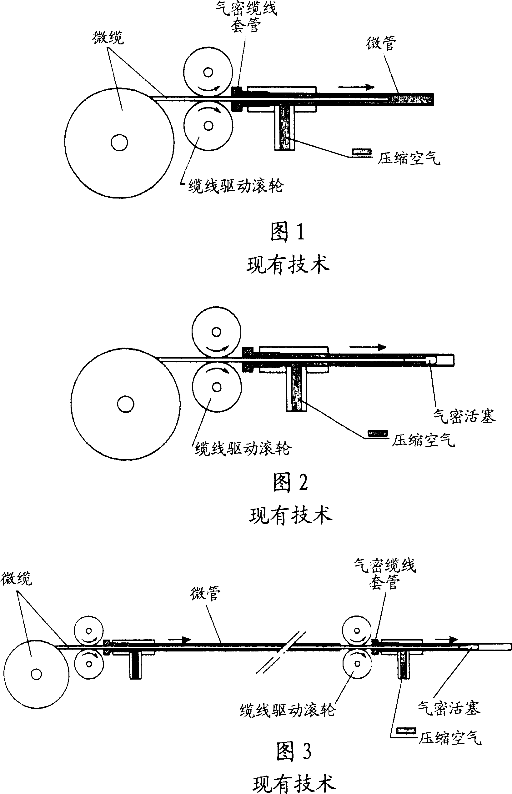
A fiber optic, friction-driven technology for fiber/cable installations, instrumentation, optics, etc., that solves the problems of not always being able to install cable ducts, air leakage, overall size and weight that cannot be easily handled

Active Publication Date: 2007-05-30
FRANCE TELECOM SA
View PDF0 Cites 0 Cited by
  • Summary
  • Abstract
  • Description
  • Claims
  • Application Information

AI Technical Summary

Problems solved by technology

Sealing problems are often encountered when the device is closed again: the necessary seals for the device cannot be properly reseated within its housing, which causes air leakage
[0012] Furthermore, known types of equipment whose dimensions are not particularly suitable for use in buildings cannot always be installed in cable ducts
Additionally, the installer cannot simply operate such equipment
In practice, such equipment cannot be easily handled due to its overall size and weight

Method used


Image

  • Small-sized micro-cable-laying device
  • Small-sized micro-cable-laying device
  • Small-sized micro-cable-laying device

Examples


Embodiment Construction

[0024] The devices described here are suitable for use in buildings. This device imparts motion to the cable and protects the cable.

[0025] The components of the device are designed and selected to make the device as compact as possible.

[0026] The cabling device is also light in weight, which facilitates its handling and use.

[0027] Thus, the cable laying device can be used in cable ducts with small dimensions and / or in cable ducts that are relatively difficult to access.

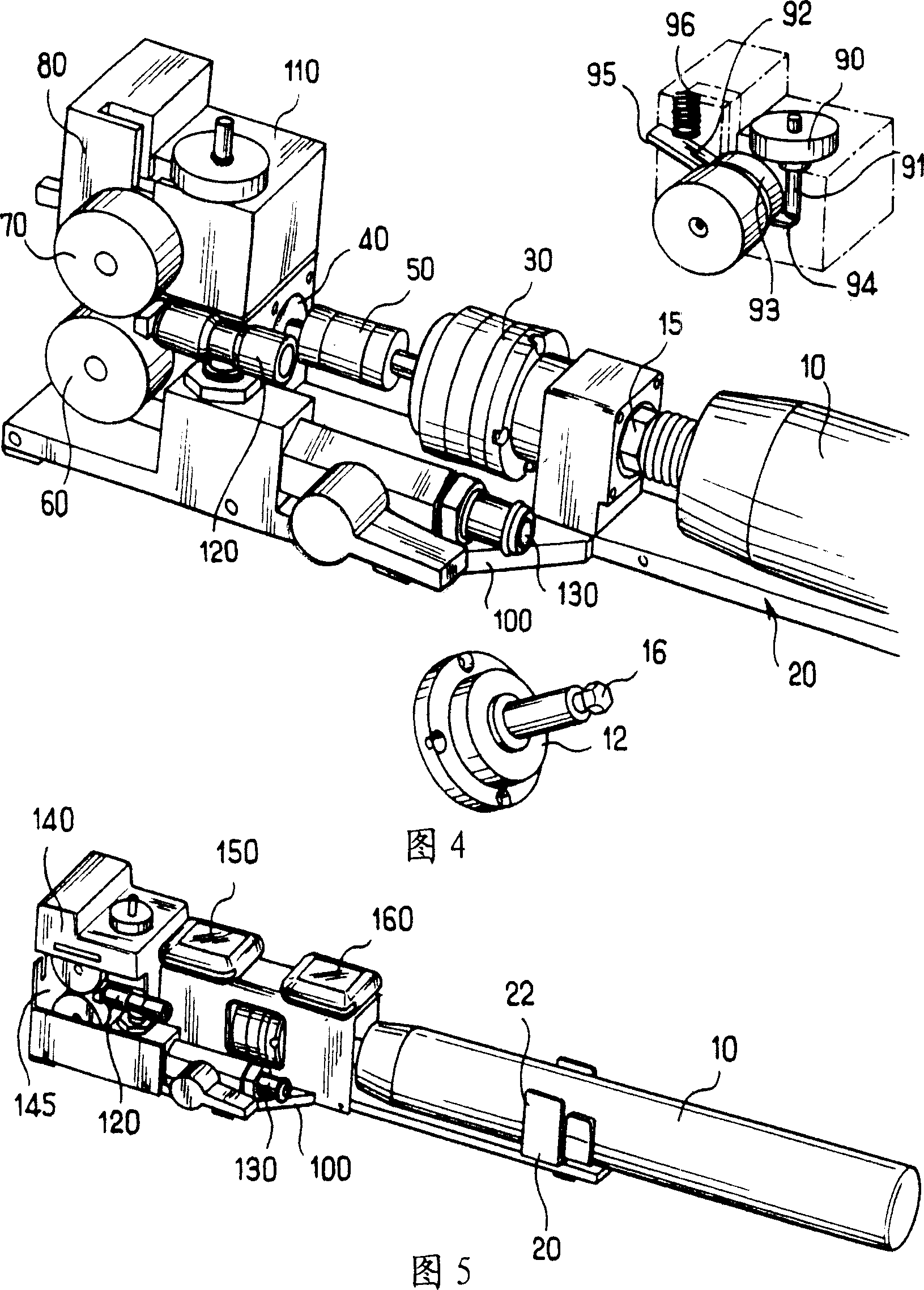
[0028] This example is designed to have a power supply from an interchangeable battery and is in the form of an ordinary handheld screwdriver body.

[0029] The screwdriver body 10 is held on a support 20 of the device which holds the motor in position, here in the form of a U-shaped member 22 clamping the two straight sides of the screwdriver. The U-shaped member prevents the screwdriver from rotating when subjected to reaction forces from the various components driven to rotate.

[0030] In the...


PUM


Abstract

The invention relates to a cable-laying device comprising fixing means for a rotary motor (10), at least one roll (60, 70) for frictionally driving a cable (200), a compressed air inlet (130) for driving said cable (200), wherein the motor fixing means, at least one said roll (60, 70) and the compressed air inlet (130) are arranged in such a way that the axis of the motor (10), the direction of the compressed air inlet (130) and the cable (200) driven by the roll (60, 70) are arranged substentially in parallel positions to each other.

Description

technical field [0001] The present invention relates to micro-cable drives for use when laying cables, in particular in buildings. Background technique [0002] Such microcable drives are used in blowing, pushing and / or pulling methods of laying cables. They are equally applicable to load bearing, pipe rodding, and push-only methods, among others. [0003] For this application, in particular the introduction of the fiber optic cable into the hollow sheath, two types of laying equipment are commercially available. [0004] The first type of laying equipment is based on the air-bearing principle (Fig. 1). These devices use air flow to let the cable out. [0005] Laying equipment of the pull and blow type (Fig. 2) causes the cable to be paid out by applying air pressure on a piston located at the head end of the cable and pushing the cable with rotating rollers. [0006] Laying installations of the type shown in FIG. 1 have been proposed for laying different types of optica...

Claims


Application Information

Patent Timeline
Patent Type & Authority Applications(China)
IPC IPC(8): G02B6/52H02G1/08G02B6/44
CPCG02B6/4464H02G1/086G02B6/52
Inventor D·勒科克C·耶维奇A-C·雷奥-托马斯
Owner FRANCE TELECOM SA
Why Eureka
Try Eureka