
CCD imaging system calibration and adjustment device

An imaging system and calibration technology, used in image analysis, image communication, image data processing, etc., can solve the problems of low measurement accuracy and poor measurement reproducibility, and achieve the goal of avoiding manual operation, easy operation, and measurement accuracy. high effect

Inactive Publication Date: 2015-04-29
中测测试科技有限公司
View PDF7 Cites 5 Cited by
  • Summary
  • Abstract
  • Description
  • Claims
  • Application Information

AI Technical Summary

Problems solved by technology

[0004] At present, the method of calibration and adjustment of CCD imaging system parameters is visual observation and manual analysis and processing. Due to the influence of human factors, the measurement reproducibility is poor and the measurement accuracy is not high.

Method used


Image

  • CCD imaging system calibration and adjustment device
  • CCD imaging system calibration and adjustment device
  • CCD imaging system calibration and adjustment device

Examples


Embodiment 1

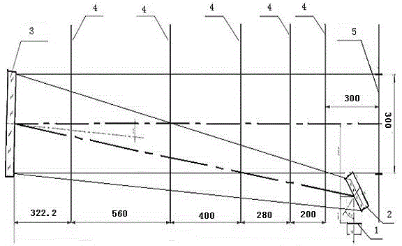
[0015] Embodiment 1: as figure 1 As shown, this embodiment provides a CCD imaging system calibration adjustment device that is less affected by human factors, has high measurement accuracy, and has a high degree of automation, including a collimator (not shown in the figure), and a front end of the collimator An exit aperture 5 is provided, and the rear end of the collimator is provided with a parabolic primary mirror 3; one side of the collimator is provided with a target 1 (the target 1 can be arbitrarily replaced according to the required test parameters), so The position of the target 1 is close to the exit diaphragm 5 and is set at 90 degrees with the exit diaphragm, and the collimator is provided with a plane secondary mirror 2, a parabolic primary mirror 3 and more than one barrier screen 4; the barrier The screen 4 is provided with a light hole. The plane secondary mirror 2 is located at the front end of the collimator and behind the exit diaphragm 5, the parabolic pr...


PUM


Abstract

The invention relates to the field of light-sensitive device performance testing, in particular to a CCD imaging system calibration and adjustment device. The CCD imaging system calibration and adjustment device comprises an integrating sphere light source and a collimator. The collimator is a shell arranged in the front-and-back direction, and the front end of the shell is provided with an outlet light bar. One side of the shell of the collimator is provided with a target, the target is close to the outlet light bar, an included angle formed between the target and the outlet light bar is 90 degrees, and a secondary plane mirror, a primary parabolic mirror and one or more baffle screens are arranged in the collimator. The baffle screens are provided with light through holes, and the primary parabolic mirror is located in the end, away from the outlet light bar, in the collimator. The multiple layers of baffle screens are adopted for shading scattered light, the influence of the scattered light on a CCD imaging system is avoided, the light direction is corrected through the light through holes in the baffle screens, the influences of manual operation are avoided as much as possible, measurement accuracy is high, various parameters can be acquired by replacing different targets, operation is easy and convenient, and the automation degree is high.

Description

technical field [0001] The invention relates to the field of performance testing of photosensitive devices, in particular to a calibration and adjustment device for a CCD imaging system. Background technique [0002] Charge Coupled Device (CCD for short, also known as CCD image sensor, image controller), is a light energy conversion device, which is made of high-sensitivity semiconductor material, which can convert light into electric charge and store it. . CCD has been widely used in camera, image acquisition, scanner and industrial measurement and other fields. [0003] A CCD imaging system refers to an optical imaging system that includes main components such as an optical lens and a CCD (usually also includes peripheral devices such as a driver and a filter); the characteristics of a CCD imaging system are determined by the system optical coaxiality, system modulation transfer function, etc. (MTF), system distortion, field of view (FOV) and focal length, system resolut...

Claims


Application Information

Patent Timeline
IPC IPC(8): H04N17/00G06T7/00
Inventor 张宪亮刘若凡苏红雨刘夏茹曾道全
Owner 中测测试科技有限公司
Learn More