Cylinder type permanent magnetic speed controller

A permanent magnet governor, cylindrical technology, applied in the direction of electrical components, electromechanical devices, etc., can solve the problems of small magnetic density, small torque density, low utilization rate of magnetic energy of permanent magnet governor, etc., to achieve large output The effect of torque

Inactive Publication Date: 2015-04-29
HENAN POLYTECHNIC UNIV
View PDF9 Cites 0 Cited by
  • Summary
  • Abstract
  • Description
  • Claims
  • Application Information

AI Technical Summary

Problems solved by technology

[0003] The magnetic energy density of the permanent magnet array in the known cylindrical permanent magnet governor is as follows figure 2 As shown, the outer magnetic conduction cylinder, the thin-walled copper cylinder, the permanent magnet block and the inner magnetic conduction cylinder, which are coaxial and arranged in sequence from outside to inside, the outer surface of the permanent magnet block and the inner surface of the thin-walled copper cylinder 2 There is an air gap between them, the permanent magnets on the permanent magnet rotor are all radially magnetized, and the magnetic density distribution is almost evenly distributed on the inner and outer sides of the permanent magnets, and the magnetic density in the working air gap is small, so the permanent magnet adjustment The magnetic energy utilization rate of the gearbox is low, and the torque density is small

Method used


Image

  • Cylinder type permanent magnetic speed controller
  • Cylinder type permanent magnetic speed controller
  • Cylinder type permanent magnetic speed controller

Examples


Embodiment Construction

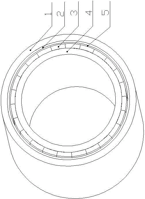
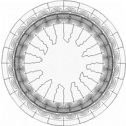
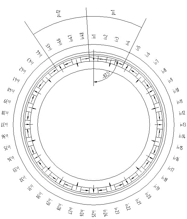
[0030] Such as figure 1 , image 3 , Figure 4 , Figure 5 , Image 6 with Figure 7 The cylinder type permanent magnet governor shown includes an outer magnetic cylinder 1, a thin-walled copper cylinder 2, a permanent magnet block 3, and an inner magnetic cylinder 4 arranged coaxially and sequentially from the outside to the inside. , The outer wall of the thin-walled copper cylinder 2 is closely attached and fixed to the inner surface of the outer magnetic permeable cylinder 1 to form the first rotor assembly, and a number of permanent magnet blocks 3 are attached and fixed on the outer side of the inner permeable cylinder 4 in the circumferential direction. The surface constitutes the second rotor assembly, the first rotor assembly and the second rotor assembly are coaxially installed, and there is an air gap 5 between the outer surface of the permanent magnet block 3 and the inner surface of the thin-walled copper cylinder 2. The outer magnetic cylinder 1 and the inner mag...


PUM


Abstract

A cylinder type permanent magnetic speed controller comprises an outer magnetic conductive cylinder, a thin-wall copper cylinder, permanent magnet blocks and an inner magnetic conductive cylinder, wherein the outer magnetic conductive cylinder, the thin-wall copper cylinder, the permanent magnet blocks and the inner magnetic conductive cylinder are arranged in sequence from outside to inside. The outer wall of the thin-wall copper cylinder is tightly attached and fixed to the inner surface of the outer magnetic conductive cylinder to form a first rotor assembly, and multiple permanent magnet blocks are attached and fixed to the outer surface of the inner magnetic conductive cylinder in the circumferential direction to form a second rotor assembly. The cross section of each permanent magnet block can be in a fan shape or other shapes, and the magnetizing direction of the permanent magnet blocks meets a given computational formula. The first rotor assembly and the second rotor assembly are mounted coaxially, and an air gap is formed between the outer surface of each permanent magnet block and the inner surface of the thin-wall copper cylinder. The cylinder type permanent magnetic speed controller has the advantages that most magnetic energy of a magnetic pole set is collected in the air gaps, the utilization rate of the magnetic energy is high, and the torque density is large. The permanent magnetic speed controller can transmit more torque or power, the structural size is small, the production cost is low, and needed mounting space is small.

Description

Technical field [0001] The invention relates to a cylindrical permanent magnet speed regulator. Background technique [0002] Cylindrical permanent magnet governor transmits motion and torque through the magnetic coupling between the main and driven rotors, and realizes the non-contact transmission of motion and force between the prime mover and the load, and has controllable start, High reliability, good environmental adaptability, and no electromagnetic interference. [0003] The magnetic energy density of the permanent magnet array in the known cylindrical permanent magnet governor is as figure 2 As shown, the outer magnetic cylinder, the thin-walled copper cylinder, the permanent magnet block and the inner magnetically conductive cylinder are arranged coaxially and sequentially from the outside to the inside, the outer surface of the permanent magnet block and the inner surface of the thin-walled copper cylinder 2 There is an air gap between them. The permanent magnets on ...

Claims


Application Information

Patent Timeline
Patent Type & Authority Applications(China)
IPC IPC(8): H02K16/00
Inventor 张海张小东闫亮郑果李新王楠楠孔新玲
Owner HENAN POLYTECHNIC UNIV
Why Eureka
Try Eureka