
A High Beam Quality Optical Filter with Multiple Gate Modes

A high beam, filter technology, applied in the fields of optical fiber components, optical spectrum control, analysis, and measurement, can solve the problems of pulse light dispersion pulse width, broadening, low contrast, etc., achieve easy spectrum control, reduce pulse width, Easy-to-control effects

Active Publication Date: 2017-03-01
江苏鲲鹏未来光学有限公司
View PDF5 Cites 0 Cited by
  • Summary
  • Abstract
  • Description
  • Claims
  • Application Information

AI Technical Summary

Problems solved by technology

[0003] For a monochromator, its exit is a slit, that is to say, only band-pass light can be obtained, and long-pass or short-pass light cannot be obtained.
Secondly, if the energy of the signal light is strong, the contrast of the light obtained by the monochromator will be low
In the rapid measurement of weak light signals, the photosensitive area of ​​the detector is usually very small. For example, the radius of the photosensitive area of ​​an avalanche photodiode (APD) is only tens of microns or even smaller. The commonly used monochromatic processed light is emitted by the slit , forming striped light spots, it is difficult to focus into a small light spot, which increases the difficulty of fast measurement in low light
In addition, it is difficult for the striped spot emitted by the monochromator to be coupled into the optical fiber, which reduces the propagation efficiency of the beam
[0004] In addition, the above-mentioned filter and monochromator will also cause the dispersion of the pulsed light to widen the pulse width

Method used


Image

  • A High Beam Quality Optical Filter with Multiple Gate Modes
  • A High Beam Quality Optical Filter with Multiple Gate Modes
  • A High Beam Quality Optical Filter with Multiple Gate Modes

Examples


Embodiment Construction

[0027] The specific implementation manner of the present invention will be further described in detail below in conjunction with the accompanying drawings and examples, but the protection scope of the present invention should not be limited thereby.

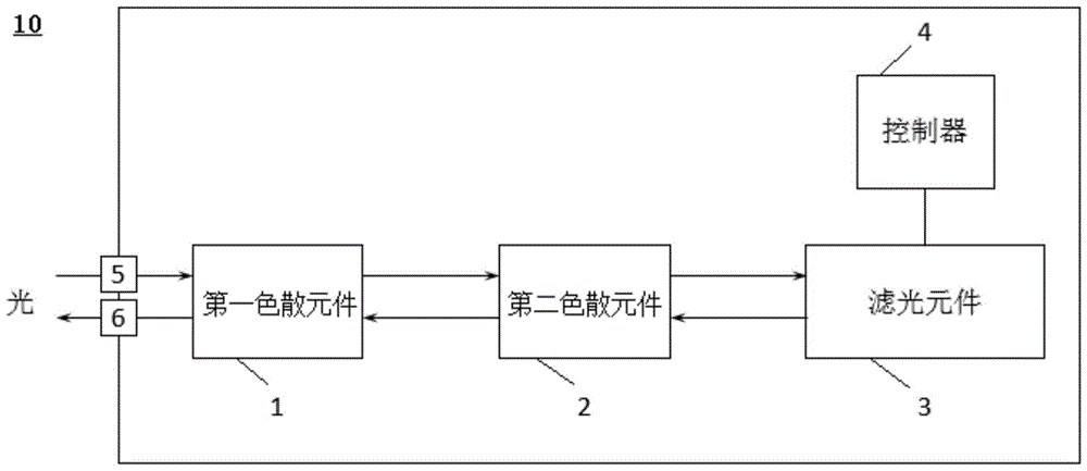
[0028] figure 1 It is a structural schematic diagram of an optical filter with multi-selection mode and high beam quality according to the present invention, the optical filter 10 includes a first dispersive element 1, a second dispersive element 2, a filter element 3, a controller 4, a beam entrance 5 and Beam exit 6.

[0029] The first dispersive element 1 is used to diverge the initial light beam into a divergent light beam, and is used to restore the gate light beam from the second dispersive element 2 . The second dispersive element 2 is used for converging the diverging light beam from the first dispersive element 1 into a parallel light beam, and converging the gating light beam from the filter element. The first dispers...


PUM


Abstract

The invention provides a light filter with multiple strobe modes and high beam quality. The light filter comprises a first dispersion element, a second dispersion element, a light filter element, a controller, a beam inlet and a beam outlet, wherein the first dispersion element is used for diverging initial beams to divergent beams and used for restoring strobe beams; the second dispersion element is used for converging the divergent beams to parallel beams and converging the strobe beams; the light filter element is used for performing strobe on beams with required wavelengths from the parallel beams from the second dispersion element to obtain strobe beams and reflecting the strobe beams to the second dispersion element; the controller is used for controlling the light filter element to perform strobe on the beams with required wavelengths; the beam outlet and the beam inlet are used for controlling incidence of the initial beams to the first dispersion element and controlling the strobe beams restored by the first dispersion element to be shot outside the light filter. The light filter can perform second-order dispersion compensation, has four strobe modes of long pass, short pass, band pass and band stop, and has adjustable wavelengths.

Description

technical field [0001] The invention belongs to the field of optical spectrum control, measurement and analysis, and the field of optical fiber components, and relates to the fields of light beam filtering, light splitting, second-order dispersion compensation, etc., and in particular to a multi-selection mode high-beam quality optical filter. Background technique [0002] At present, the filter elements used in biochemical spectral analysis are mainly optical filters and monochromators, each of which has its own limitations. For optical filters, the wavelength selection of ordinary optical filters cannot be adjusted, and it is difficult to control the spectrum; in spectral analysis, it is necessary to prepare a variety of required optical filters, and frequent replacement of optical filters also increases the burden on spectral analysis. workload. Secondly; when the energy of the light source is strong, the filter is easily damaged or the use time is greatly reduced. [0...

Claims


Application Information

Patent Timeline
Patent Type & Authority Patents(China)
IPC IPC(8): G02B26/02
Inventor 潘海峰贾梦辉张三军李磊曹晓丹徐建华
Owner 江苏鲲鹏未来光学有限公司
Learn More