A sand box flip cleaning device for iron mold casting production line

A casting production line, inversion cleaning technology, applied in the direction of mold box, casting molding equipment, manufacturing tools, etc., to achieve the effect of eliminating potential safety hazards, realizing continuous operation, and simple device structure

Active Publication Date: 2016-11-23
湖州鼎盛机械科技股份有限公司
View PDF8 Cites 0 Cited by
  • Summary
  • Abstract
  • Description
  • Claims
  • Application Information

AI Technical Summary

Problems solved by technology

[0006] In order to solve the defect that the existing sand foundry device needs hoisting equipment to lift the sand box, the invention provides a sand box flipping and cleaning device for an iron mold casting production line. This greatly simplifies the operation steps, eliminates potential safety hazards, and improves the flipping efficiency of the sand box. At the same time, the sand box is cleaned to remove the residual sand, so that the sand box can be used directly.

Method used


Image

  • A sand box flip cleaning device for iron mold casting production line
  • A sand box flip cleaning device for iron mold casting production line
  • A sand box flip cleaning device for iron mold casting production line

Examples


Embodiment 1

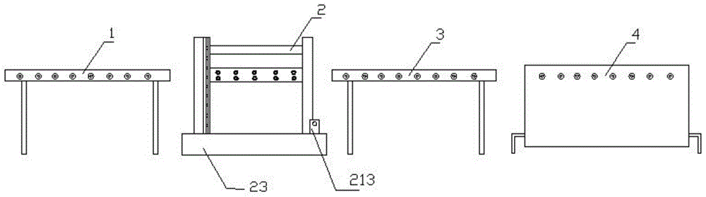
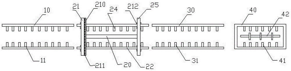
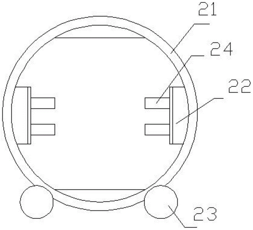
[0035] This embodiment includes a sand box feeding mechanism 1, a sand box turning mechanism 2, a sand box sending mechanism 3 and a sand box cleaning mechanism. According to the running direction of the sand box, the sand box sending mechanism 1 is located in front of the sand box turning mechanism 2, The sand box sending mechanism 3 is positioned at the rear of the sand box turning mechanism 2, and the sand box cleaning mechanism 4 is positioned at the rear of the sand box sending mechanism 3. Frame 23 and the rotating ring driving device that drives the rotating ring to rotate. Rotate on frame 23, described sand box support plate 22 is provided with roller table 24, and roller table 24 is made of a plurality of rollers. A plurality of rollers of the roller table 24 are driven by a roller table driving device, and the sand box is sent out by the rotation of the rollers. The sand box cleaning mechanism 4 includes a cleaning tank 40, a cleaning roller table 41 and a water spra...

Embodiment 2

[0044] This embodiment includes a sand box feeding mechanism 1, a sand box turning mechanism 2, a sand box sending mechanism 3 and a sand box cleaning mechanism. According to the running direction of the sand box, the sand box sending mechanism 1 is located in front of the sand box turning mechanism 2, The sand box sending mechanism 3 is positioned at the rear of the sand box turning mechanism 2, and the sand box cleaning mechanism 4 is positioned at the rear of the sand box sending mechanism 3. Frame 23 and the rotating ring driving device that drives the rotating ring to rotate. Rotate on frame 23, described sand box support plate 22 is provided with roller table 24, and roller table 24 is made of a plurality of rollers. The sand box on the sand box feeding mechanism 1 pushes the sand box on the sand box turning mechanism 2 to the sand box output mechanism 3, thereby realizing the continuous operation of the sand box turning. The sand box cleaning mechanism 4 includes a cle...


PUM


Abstract

The invention relates to a sand box overturn cleaning device for an iron mold casting production line. The device comprises a sand box feeding mechanism, a sand box overturn mechanism, a sand box delivery mechanism and a sand box cleaning mechanism; according to the travelling direction of a sand box, the sand box feeding mechanism is arranged in front of the sand box overturn mechanism, the sand box delivery mechanism is arranged behind the sand box overturn mechanism, and the sand box cleaning mechanism is arranged behind the sand box delivery mechanism. Lifting equipment does not need to be used for lifting when the sand box is overturned, the operation step is greatly simplified, the safety loophole is eliminated, the sand box overturn efficiency is improved, and the sand box is cleaned at the same time; the residual sand can be removed, so that the sand box can be directly used.

Description

technical field [0001] The invention relates to casting equipment, in particular to a device for flipping and cleaning a sand box used in an iron mold casting production line. Background technique [0002] Sand Casting - A casting method in which castings are produced in sand molds. Steel, iron and most non-ferrous alloy castings can be obtained by sand casting. Because the molding materials used in sand casting are cheap and easy to obtain, the casting mold is easy to manufacture, and it can adapt to the single-piece production, batch production and mass production of castings. It has been the basic process in casting production for a long time. [0003] After the sand casting is completed, the sand in the sand box needs to be poured out and recycled for reuse. In the existing foundry production line, the sand box turning device is commonly used to complete this process. [0004] The authorized announcement number is CN203221185U, and the authorized announcement date is ...

Claims


Application Information

Patent Timeline
Patent Type & Authority Patents(China)
IPC IPC(8): B22C25/00
CPCB22C21/12
Inventor 邱仲华钱根荣
Owner 湖州鼎盛机械科技股份有限公司
Why Eureka
Try Eureka