A desulfurization device and desulfurization method

A desulfurization device, a square technology, applied in separation methods, chemical instruments and methods, dispersed particle separation, etc., can solve the problems of poor boiler combustion stability, unfavorable implementation, impact and damage of reaction gas flow balance, etc., to avoid insufficient desulfurization efficiency, The effect of improving the gas-solid separation efficiency and reducing the ash powder escape rate

Active Publication Date: 2017-02-22
HENAN SHENMA NYLON CHEM
View PDF5 Cites 0 Cited by
  • Summary
  • Abstract
  • Description
  • Claims
  • Application Information

AI Technical Summary

Problems solved by technology

"However, the actual operation situation is that most of the limestone particle size below 1.0mm escapes with the fly ash in the square separator, and the separation efficiency is low in industrial applications. Although the square separator has technical advantages such as low manufacturing cost and convenient maintenance and implementation , but it has gradually shown its unfavorable side in the existing industrial applications
[0005] The conventional limestone inlets of the current circulating fluidized bed boilers are generally set at the furnace roof, the side of the water wall, and the inclined legs of the return material, which may easily cause poor combustion stability of the boiler, and are prone to unfavorable problems such as fire extinguishing, coking, and wear of the furnace wall; The location is relatively high. Theoretically, the recycled limestone powder is easy to escape with the airflow during the process of entering the high-temperature furnace from top to bottom, resulting in a low actual utilization rate. Impact and damage the already formed reaction gas flow balance, interfere with the progress of the desulfurization reaction, which is not conducive to the improvement and stability of the reaction efficiency

Method used


Image

  • A desulfurization device and desulfurization method
  • A desulfurization device and desulfurization method
  • A desulfurization device and desulfurization method

Examples


Embodiment 1

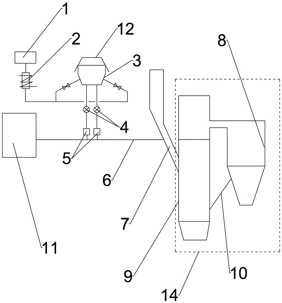
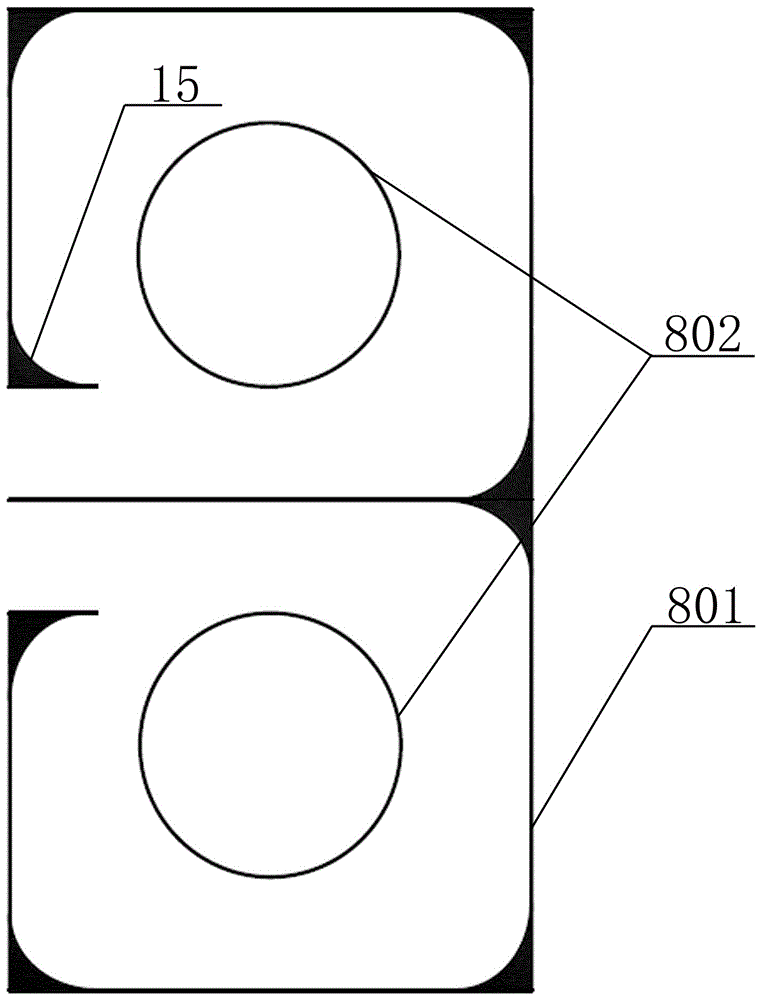
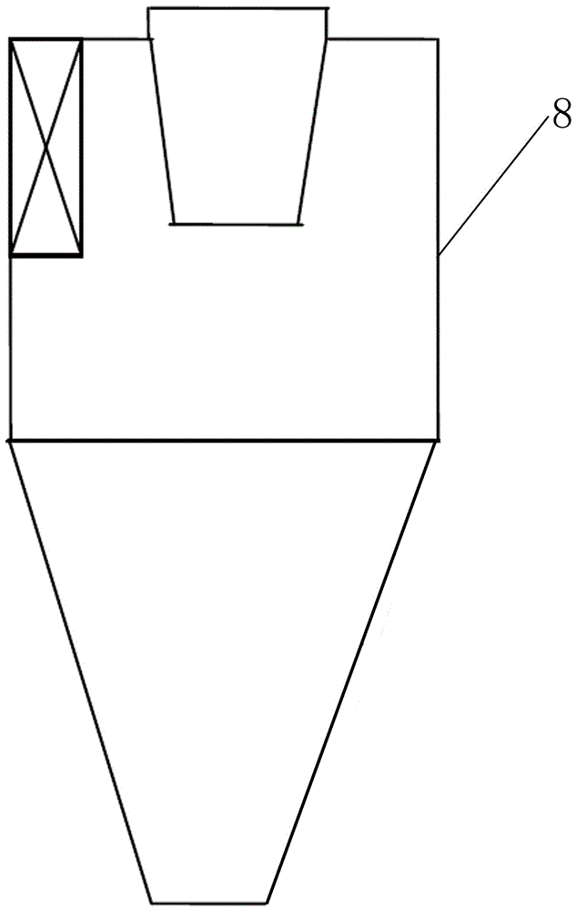
[0027] like figure 1 As shown in -5, a desulfurization device includes a fan 1, a limestone bin 3, a gas storage tank 11 and a circulating fluidized bed boiler 14, and the circulating fluidized bed boiler 14 includes a furnace 9, a return pipe 10 and a square separator 8, The upper part of the square separator 8 communicates with the upper part of the furnace 9; the inside and outside of the square separator 8 are respectively a central cylinder 802 and a square water cooling screen 801, the upper part of the central cylinder 802 is a cylindrical structure, and the lower part is a top-to-bottom The frustum of a cone structure that closes downwards (the diameter ratio of the upper and lower parts of the frustum of the cone structure is 10:7, and the height ratio of the upper and lower parts of the central tube is 1:7); the right-angled surfaces of the inner surface of the square water-cooling screen 801 are respectively fastened A wear-resistant material layer (made of corundum...

Embodiment 2

[0033] The difference between the desulfurization device used in embodiment 2 and embodiment 1 is that: the angle between the feed pipe 4 and the coal drop pipe 7 is 50°, the diameter ratio of the upper and lower sides of the frustum of conical structure is 10:6, and the center The height ratio of the upper and lower parts of the cylinder is 1:10.

[0034] The desulfurization method in Example 2 is different from the desulfurization method used in Example 1 in that: keep the temperature inside the circulating fluidized bed boiler at 950°C, desulfurize and denitrify the coal fired; the S content of the incoming coal is 0.91% , the particle size of limestone is 1.5-2.5mm, the effective CaCO 3 The content is 60%, and the bulk density is 1.25t / m 3 , the conveying speed of limestone is 14m / s, the gas-solid ratio is 1:3, and the original emission of flue gas is SO 2 Concentration 4137mg / m 3 , SO in flue gas emission after desulfurization 2 Concentration 82mg / m 3 , the achieved...

Embodiment 3

[0038] The difference between the desulfurization device used in Example 3 and Example 1 is that the angle between the feed pipe 4 and the coal drop pipe 7 is 45°, the diameter ratio of the upper and lower sides of the frustum of conical structure is 10:8, and the center The height ratio of the upper and lower parts of the cylinder is 1:3.

[0039] The desulfurization method of embodiment 3 is different from the desulfurization method used in embodiment 1 in that: the temperature in the furnace 9 of the circulating fluidized bed boiler is kept at 900 ° C, and the coal is desulfurized and denitrified; the S content of the coal entering the furnace is 0.39%, the particle size of limestone is 1.5-2.5mm, and the bulk density is 1.2t / m 3 , effective CaCO 3 The content is 50%. The conveying speed of limestone is 14m / s, the gas-solid ratio is 1:6, and the original emission of flue gas is SO 2 Concentration 2313mg / m 3 , SO in flue gas emission after desulfurization 2 Concentrati...


PUM


Abstract

The invention provides a desulfurization device. The desulfurization device comprises a draught fan, a lime stone cabin, a gas storage tank and a circulating fluidized bed boiler, and is characterized in that the circulating fluidized bed boiler comprises a hearth, a material returning pipe and a square separator, wherein the upper part of the square separator is communicated with the upper part of the hearth; the lower part of the square separator is connected with the lower part of the hearth by the material returning pipe and a coal falling pipe is arranged on the hearth; the draught fan is connected with the bottom of the lime stone cabin by a heating device; the upper part of the lime stone cabin is connected with a bag dust remover and the lower end of the lime stone cabin is connected with a feeding machine by an unloading valve; the feeding machine is connected with a feeding pipe; the gas storage tank is connected with the feeding pipe and the feeding pipe is connected with the coal falling pipe. The invention further provides a desulfurization process utilizing the desulfurization device; the conveying speed of lime stones is 12m / s-14m / s and the gas-solid ratio is 1 to (3-6). The production cost of the equipment is reduced, the desulfurization effect of the circulating fluidized bed boiler is improved and the economic benefits are good.

Description

technical field [0001] The invention belongs to the technical field of boiler equipment, and in particular relates to a desulfurization device and a desulfurization method. Background technique [0002] There are various coal-fired desulfurization methods for boilers. Among them, circulating fluidized bed boilers (CFB boilers for short) are one of the more mature clean combustion methods. They have good environmental protection performance and can easily achieve desulfurization in the furnace. They have developed rapidly in China. In particular, the CFB dry desulfurization device is widely used due to its advantages of small investment, low operating cost, and no secondary pollution. [0003] At present, the separators used in the combustion technology of circulating fluidized bed boilers are mostly circular separators. The manufacturing of circular separators is difficult and costly. The requirements for the accuracy of limestone particle size are high, and the cost of indu...

Claims


Application Information

Patent Timeline
Patent Type & Authority Patents(China)
IPC IPC(8): B01D53/83B01D53/50F23J15/02
Inventor 李本斌陈聚良陈桂昌周丽莉华旭霞段文蕊张乐堂张佩兰郑黎胡文杰赵红岩巩建华杨晓丹李义
Owner HENAN SHENMA NYLON CHEM
Why Eureka
Try Eureka