Water filtering type air clarifying device
An air purification device and water filter technology, which is applied in the field of air purification filter devices and water filter air purification devices, can solve the problems of high gas-solid separation efficiency, unsatisfactory dry filtration method, and small pressure loss, and achieve gas-solid separation. High separation efficiency, high cost performance, and low pressure loss
- Summary
- Abstract
- Description
- Claims
- Application Information
AI Technical Summary
Problems solved by technology
Method used
Image

Examples
specific Embodiment 1
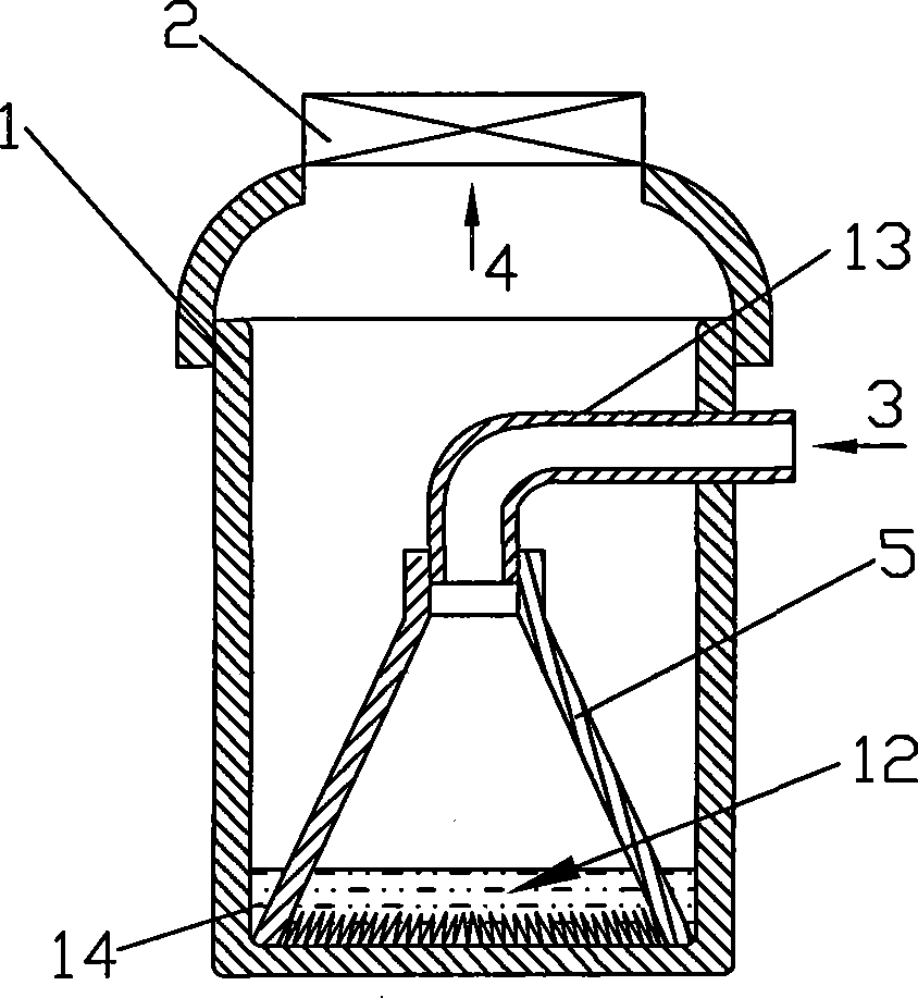
[0035] Reference figure 1 , Figure 9 and Picture 10 This embodiment includes a container 1 and an exhaust fan 2. The container 1 is provided with an air inlet 3 and an air outlet 4. The air outlet 4 of the container 1 is directly connected with the exhaust fan 2, and the inner cavity of the container 1 is provided with an air duct 5 and water 12 The air duct 5 is provided with a narrow opening 53 and a wide opening 52. The narrow opening 53 of the air duct 5 is upwards. The narrow opening 53 is connected to the air inlet 3 of the container 1 through the ventilation tube 13, and the air duct 13 is inserted into the air duct. In the narrow mouth 53; the open mouth of the container 1 is used as the air outlet 4, and the air outlet 4 is directly connected with the suction port of the exhaust fan 2. The wide opening 52 of the air duct 5 is downwards, and the outer edge of the largest outer diameter portion thereof is in contact with the inner side wall of the container 1. A number of ...
specific Embodiment 2
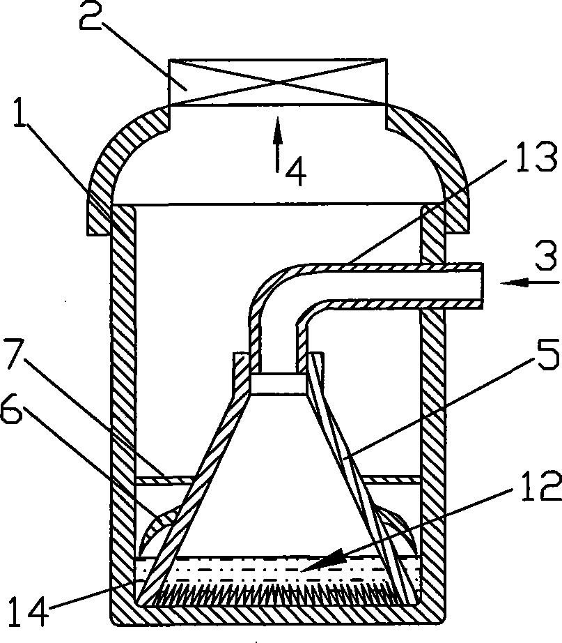
[0041] The characteristics of this embodiment are: refer to figure 2 In this embodiment, a dispersion baffle 6 is provided on the outer wall of the wide mouth portion of the cone-shaped air duct 5. The diameter of the baffle 6 is slightly smaller than the inner diameter of the container 1, and the edge of the port and the inner wall of the container 1 form a slit. The dispersion baffle 6 can be horizontal, arc-shaped, or 10°-180° curved. A dispersion net 7 is provided above the baffle 6. The dispersing net 7 is composed of a single net. The rest can be the same as the specific embodiment 1.
[0042] The working principle of this embodiment is as follows:
[0043] Turn on the exhaust fan, the air is driven by negative pressure into the air inlet 3, decelerates to the water surface through the conical air duct 5, and then accelerates through the air hole 51 and the water in the slit 14 between the outer wall of the conical air duct 5 and the inner wall of the container 1 ( Narrow ar...
specific Embodiment 3
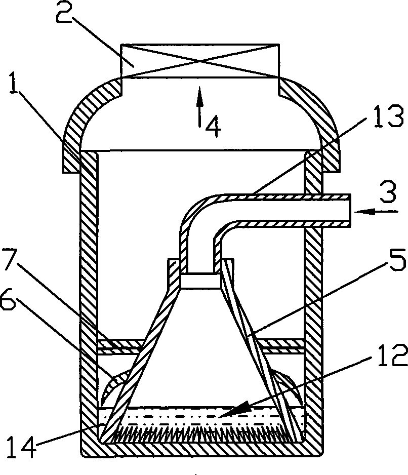
[0044] The characteristics of this embodiment are: refer to image 3 A dispersing baffle 6 is provided on the outer wall of the wide mouth portion of the conical air duct 5, the diameter of the baffle 6 is slightly smaller than the inner diameter of the container 1, and the edge of the port and the inner wall of the container 1 form a slit. The dispersion baffle 6 can be horizontal, arc-shaped, or 10°-180° curved. A dispersion net 7 is provided above the baffle 6. The dispersing net 7 is composed of two upper and lower nets. The rest can be the same as the specific embodiment 1.
[0045] The working principle of this embodiment is as follows:
[0046] Turn on the exhaust fan, the air is driven by negative pressure into the air inlet 3, decelerates to the water surface through the conical air duct 5, and then accelerates through the air hole 51 and the water in the slit 14 between the outer wall of the conical air duct 5 and the inner wall of the container 1 ( Narrow area) mixed. T...
PUM
 Abstract
Description
Claims
Application Information
 - R&D
- Intellectual Property
- Life Sciences
- Materials
- Tech Scout
- Unparalleled Data Quality
- Higher Quality Content
- 60% Fewer Hallucinations
Browse by: Latest US Patents, China's latest patents, Technical Efficacy Thesaurus, Application Domain, Technology Topic, Popular Technical Reports.
© 2025 PatSnap. All rights reserved.Legal|Privacy policy|Modern Slavery Act Transparency Statement|Sitemap|About US| Contact US: help@patsnap.com