Large-tonnage integral cab structure

A cab and integral technology, applied to the upper structure, upper structure of trucks, vehicle components, etc., can solve the problems of many openings on the cab, cab impact deformation, cab deformation, etc., to achieve shock absorption Good noise reduction effect, good overall sealing performance, and high anti-rolling strength

Inactive Publication Date: 2015-04-22
XCMG CONSTR MACHINERY
View PDF6 Cites 1 Cited by
  • Summary
  • Abstract
  • Description
  • Claims
  • Application Information

AI Technical Summary

Problems solved by technology

However, due to the harsh working environment of the loader, the cab with this structure is prone to being crushed or deformed by impact
For example, in a mine, once falling objects collapse, the cab will be directly deformed or even flattened; while in mines with bad road conditions, once a rollover occurs, the cab will be deformed or broken by impact, which is harmful to the driver. There is a great threat, so the strength of the cab of this structure is too low, not suitable for use in mines or on mines
In order to increase the strength of the cab, the frame is generally welded inside the thin plate parts of the cab, but the openings on the frame are not concentric with the punched holes on the sheet metal parts. The workers need to ream the holes on site when welding, and the reaming will Increase the working hours and weaken the stability of the skeleton, the increased strength is limited, and the expected effect cannot be achieved
[0003] In addition, the existing cab also has the following problems: 1. The appearance is not aesthetically pleasing; 2. There are too many holes in the cab, which makes the sealing of the cab not good, and noise, rain, and dust can easily enter the cab, causing customers complaint

Method used


Image

  • Large-tonnage integral cab structure
  • Large-tonnage integral cab structure
  • Large-tonnage integral cab structure

Examples


Embodiment Construction

[0018] The present invention will be further described below in conjunction with accompanying drawing.

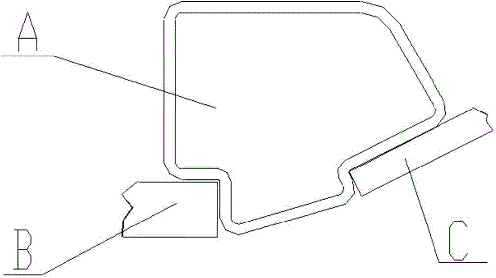
[0019] Such as figure 1 As shown, a large-tonnage integrated cab structure includes a skeleton and sheet metal parts welded on the skeleton. The skeleton is welded by special-shaped pipes and rectangular pipes. The room is streamlined.

[0020] The frame includes a bottom frame 6, a top frame 5, a rear column 1, an upper middle column 2, a lower middle column 3, and a front column 4. Both the bottom frame 6 and the top frame 5 are welded into a "well"-shaped structure with rectangular tubes , the front column 4 is formed by bending special-shaped tubes; the floor is welded on the bottom frame 6, the front column 4 and the rear column 1 are welded on the front and rear ends of the bottom frame 6, and the middle and lower columns 3 are welded on the bottom frame 6 and On the rear column 1, the middle and upper columns 2 are welded on the middle and lower columns 3, and the ...


PUM


Abstract

The invention discloses a large-tonnage integral cab structure. A cab welding assembly is mainly formed by welding a framework and sheet metal parts, and lug plate reinforcing ribs are welded to the connecting positions of the framework. A whole cab is in a streamline type. The cab has certain strength, can be used under coal mines and in mines with bad road conditions, and is beautiful in appearance molding. A framework type rolling preventing structure is adopted, the structure is formed by welding special-shaped pipes and rectangular pipes, a bottom framework body is a reinforced rectangular pipe, and the strength of the cab is guaranteed. A front wall is formed by being stamped by a die, a covering piece is welded to the framework, the sealing performance is good, shock absorption and noise reduction are achieved, welding of the framework and the sheet steel parts is located through process steps of the structures of themselves, and the framework welding assembly structure has the functions of preventing rolling and object falling.

Description

technical field [0001] The invention relates to a driver's cab, in particular to a large-tonnage integrated driver's cab structure, which belongs to the technical field of construction machinery manufacturing. Background technique [0002] At present, as an important part of construction machinery, the loader cab is welded by thin plate parts, and its main function is to provide the driver with a safe and comfortable operating environment. However, due to the harsh working environment of the loader, the cab with this structure is prone to being crushed or deformed by impact. For example, in a mine, once falling objects collapse, the cab will be directly deformed or even flattened; while in mines with bad road conditions, once a rollover occurs, the cab will be deformed or broken by impact, which is harmful to the driver. There is a great threat, so the strength of the cab of this structure is too low, and it is not suitable for use under the mine or on the mine. In order t...

Claims


Application Information

Patent Timeline
IPC IPC(8): B62D33/06
CPCB62D33/06
Inventor 路振坡王猛王振清晁靖李喆付森林徐丹吴闯
Owner XCMG CONSTR MACHINERY
Why Eureka
Try Eureka