
Microwave GaAs substrate on-chip S parameter microstrip line TRL (transistor resistor logic) calibrating member

A technology of microstrip lines and calibration components, which is applied in the field of microwave/millimeter wave S-parameter testing, and can solve problems such as the inability to achieve accurate measurement of microstrip line structures

Active Publication Date: 2015-04-08
THE 13TH RES INST OF CHINA ELECTRONICS TECH GRP CORP
View PDF5 Cites 27 Cited by
  • Summary
  • Abstract
  • Description
  • Claims
  • Application Information

AI Technical Summary

Problems solved by technology

[0011] At present, the standard samples made by Cascade and NIST using the coplanar waveguide structure, due to the different structure of the substrate and the transmission line, the accurate measurement of the microstrip line structure DUT cannot be realized after calibration with the current existing calibration parts
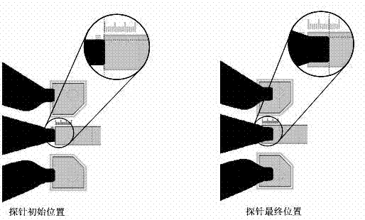
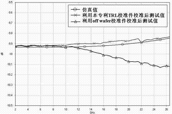
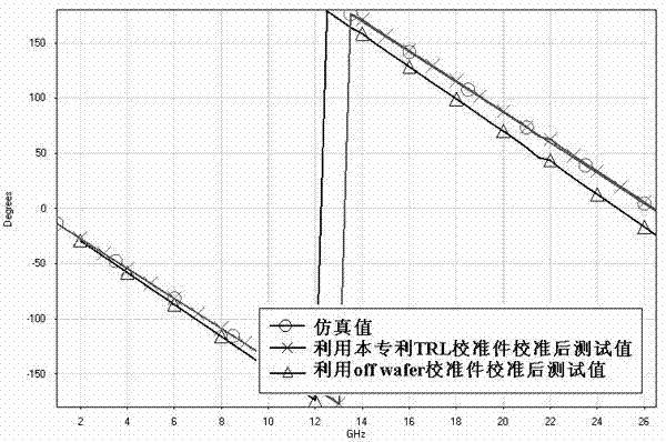
Its existing calibration kit is a general calibration kit, which can calibrate the reference plane to the probe head, and the measured data after calibration is the S parameter of the part between the input and output two probe heads. At present, most microwave single-chip products are tested These S parameters are all measured; however, when extracting the parameters of the microwave transistor die model, it is not expected that the S parameters measured after calibration include the influence of the probe pressure point and its nearby microstrip transmission line, and only hope to obtain the transistor pure Die S-parameters

Method used


Image

  • Microwave GaAs substrate on-chip S parameter microstrip line TRL (transistor resistor logic) calibrating member
  • Microwave GaAs substrate on-chip S parameter microstrip line TRL (transistor resistor logic) calibrating member
  • Microwave GaAs substrate on-chip S parameter microstrip line TRL (transistor resistor logic) calibrating member

Examples


Embodiment Construction

[0027] The present invention will be described in further detail below in conjunction with the accompanying drawings and specific embodiments.

[0028] Such as figure 1As shown, the present invention is an on-chip S-parameter microstrip line TRL calibrator based on a microwave GaAs substrate, comprising a GaAs substrate layer 2, the lower surface of the GaAs substrate layer 2 is connected with a metal layer 1, and the upper surface is provided with a through The graphic structure of the standard part Thru, the reflective standard part Reflect and the transmission line standard part Line, the ground pressure points 6 of the straight-through standard part Thru, the reflective standard part Reflect and the transmission line standard part Line respectively pass through the grounding column 7 and the The metal layer 1 is connected, and the GaAs substrate layer 2 is provided with a ground via hole compatible with the ground column 7; the characteristic impedance of the through stand...


PUM

PropertyMeasurementUnit
Thicknessaaaaaaaaaa
Thicknessaaaaaaaaaa
Lengthaaaaaaaaaa

Abstract

The invention discloses a microwave GaAs substrate on-chip S parameter microstrip line TRL (transistor resistor logic) calibrating member and relates to the technical field of microwave or millimeter-wave S parameter testing. The microwave GaAs substrate on-chip S parameter microstrip line TRL calibrating member comprises a GaAs substrate layer, the lower surface of the GaAs substrate layer is connected with a metal layer, graph structures of a direct-through standard member Thru, reflection standard members Reflect and a transmission line standard member Line are arranged on the upper surface of the GaAs substrate layer, ground voltage points of the direct-through standard member Thru, the reflection standard members Reflect and the transmission line standard member Line are connected with the metal layer through grounding columns penetrating the GaAs substrate layer respectively, and the GaAs substrate layer is provided with grounding through holes matched with the grounding columns. The microwave GaAs substrate on-chip S parameter microstrip line TRL calibrating member is manufactured by adopting a GaAs tape-out process identical with a tested member. By using the calibrating member when microwave single-chip circuit tube core model parameters are extracted, a reference plane after calibration can be positioned at the root of a tube core, so that model extracting accuracy is improved.

Description

technical field [0001] The invention relates to the technical field of microwave / millimeter wave S parameter testing. Background technique [0002] On-chip testing (directly testing the electrical characteristics of bare chips of integrated devices) technology is a new testing technology widely used in the research and production of MMICs and high-speed integrated circuits. Common chip test parameters include DC parameters (voltage, current, capacitance, etc.) and microwave parameters (S parameters, power, noise, etc.). Taking microwave S-parameters as an example, the required test instrument is usually a vector network analyzer, and its input / output ports are usually coaxial and waveguide, which cannot be directly connected to the chip. Before the invention of the microwave probe head, the S-parameter test of the chip was carried out on the test fixture after packaging. Obviously, the measurement results included the packaged probe tip and the probe head, which realized th...

Claims


Application Information

Patent Timeline
IPC IPC(8): G01R35/00
Inventor 刘晨梁法国吴爱华孙静孙晓颖栾鹏
Owner THE 13TH RES INST OF CHINA ELECTRONICS TECH GRP CORP
Learn More