


Quick Research
Generate reliable direction feasibility study reports for your R&D in just a few steps.

Technical Q&A
Discover and master advanced knowledge NOW. Basics, ideas, possibilities, all at once.

Find Solutions
As an expert in R&D theories, this can generate solutions to your technical problems instantly.

Evaluate Feasibility
Analyze your overall solution with one click, know your potential R&D risks in advance.

Monitor Landscape
Get weekly tech updates, stay abreast of the latest tech innovations and key insights.
Actuating device for a master brake cylinder of a motor vehicle
A master brake cylinder and control device technology, applied in the direction of brake transmission, brakes, vehicle components, etc., can solve problems such as complex structures, achieve the effect of less quantity, processing and assembly costs, and save space
- Summary
- Abstract
- Description
- Claims
- Application Information
AI Technical Summary
Problems solved by technology
Method used
Image

Examples
Embodiment Construction
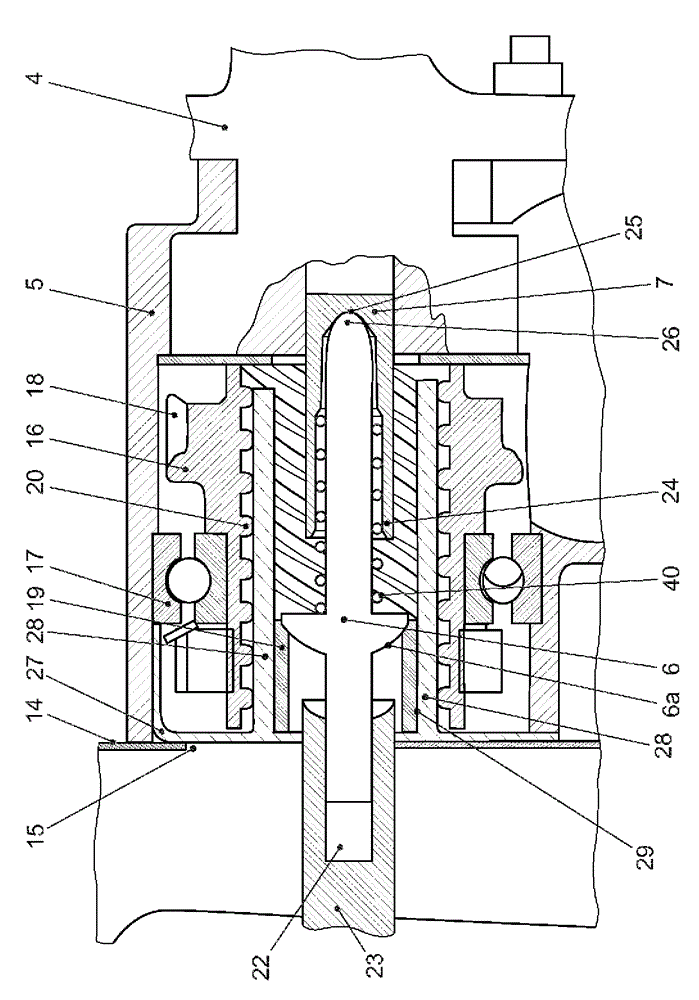
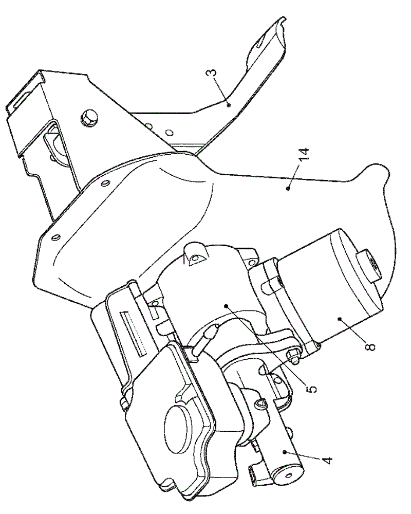
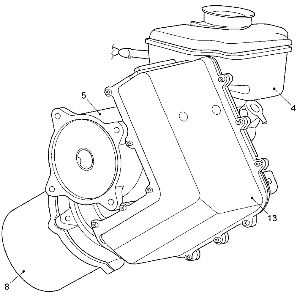
[0036] The first exemplary embodiment relates to a braking system 1 for a motor vehicle. The brake system 1 includes an electromechanical actuating device 2 which is arranged between a brake pedal 3 and a master brake cylinder 4 . An ESP hydraulic system unit of a known design, not shown in further detail, is coupled to master brake cylinder 4 in order to adjust the brake pressure on the wheel brakes of the motor vehicle on a wheel-by-wheel basis.
[0037]The electromechanical actuating device 2 is actuated by the driver as a function of the brake pedal 3 in order to provide a braking force. For this purpose, the position of brake pedal 3 is detected by means of a position sensor. The position sensor can be embodied as an angle of rotation sensor, for example. However, it is also possible to detect the brake pedal position by means of a linear displacement sensor. Alternatively or additionally, an actuating force F exerted by the driver on brake pedal 3 can be determined by...
PUM
 Abstract
Description
Claims
Application Information
 - R&D Engineer
- R&D Manager
- IP Professional
- Industry Leading Data Capabilities
- Powerful AI technology
- Patent DNA Extraction
Browse by: Latest US Patents, China's latest patents, Technical Efficacy Thesaurus, Application Domain, Technology Topic, Popular Technical Reports.
© 2024 PatSnap. All rights reserved.Legal|Privacy policy|Modern Slavery Act Transparency Statement|Sitemap|About US| Contact US: help@patsnap.com