Compensation container for cooling systems of internal combustion engines

A technology of cooling system, internal combustion engine, applied in the direction of engine cooling, machine/engine, mechanical equipment, etc., can solve problems such as uncontrollable, functional damage, etc.

Active Publication Date: 2018-01-12
KUNST SCHWANDEN
View PDF5 Cites 0 Cited by
  • Summary
  • Abstract
  • Description
  • Claims
  • Application Information

AI Technical Summary

Problems solved by technology

However, the welded connection on the inner cavity of the container is inaccessible and therefore uncontrollable
Furthermore, it is damaged due to deformation of the container during temperature and pressure fluctuations that occur during operation, so that the function of the walls of such an interior is impaired

Method used


Image

  • Compensation container for cooling systems of internal combustion engines
  • Compensation container for cooling systems of internal combustion engines
  • Compensation container for cooling systems of internal combustion engines

Examples


Embodiment Construction

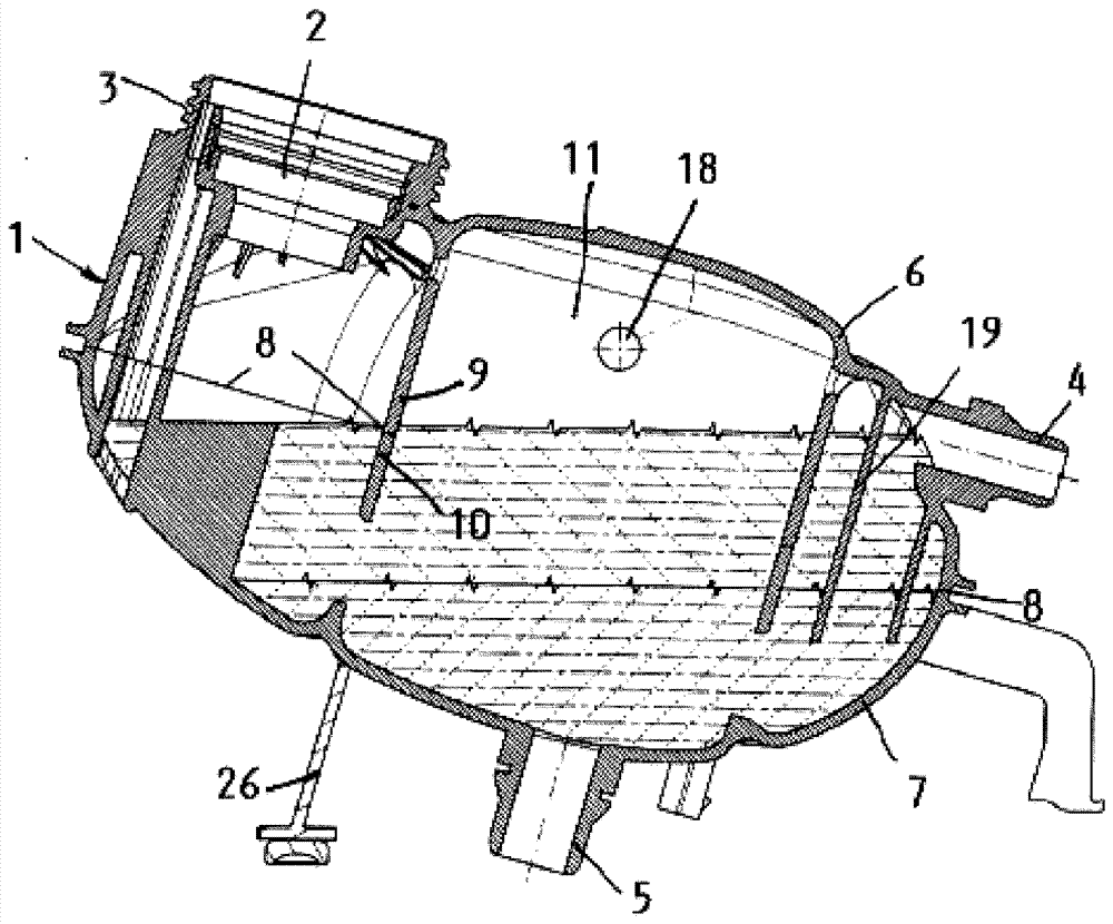
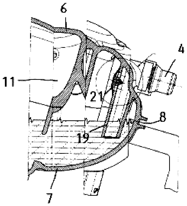
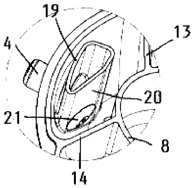
[0011] The compensating container or compensating container (Ausgleichsbehälter) 1 has an upper filling opening 2 with a connection piece 3 which is provided for receiving and locking a closure cap equipped with a pressure relief valve. For the hose connection to the cooling system of the internal combustion engine, the compensation container 1 also has upper and lower connecting lines 4 , 5 .

[0012] Due to the large temperature and pressure differences that occur in the cooling system, the compensating container 1 is subjected to high loads. Due to its design in the plastic injection molding process from two arched container shells 6 , 7 which are connected to one another via welding, and due to the resulting spherical or oval shape, it is possible at relatively low material costs The corresponding forces are absorbed without loss. Furthermore, the container housings 6 , 7 have annular inner walls 9 , 10 extending perpendicularly to the connecting surface 8 between them, b...


PUM


Abstract

The compensating container of the cooling system of the internal combustion engine comprises a domed lower container shell and an upper container shell (6, 7) constructed in plastic injection molding technology with inner walls (9, 10, 13, 14) along the Weld its edges (8) to each other. It also includes upper and lower connecting pipes (4, 5) and a sealable charging port (2). The inner wall of the compensation container extends perpendicularly to a plane containing the edge of the container shell, thereby forming at least one inner cavity (11) spaced from the outer periphery of the container, which communicates with at least one outer cavity (15, 16, 17) through an opening (18) connect. The upper connecting pipe transitions in the vessel (1) into an immersion channel (19) integrally formed with the upper vessel shell, the immersion channel extending down to the liquid-filled liquid of the lower vessel shell through the plane between the two vessel shells in the outer cavity (16). Containers are particularly effective at separating cooling liquid and air in cooling systems.

Description

technical field [0001] The invention relates to a compensating container for a cooling system of an internal combustion engine, which comprises: a lower container shell and an upper container shell with an inner wall and an arched shape constructed by plastic spraying technology, said container shells are welded to each other along their edges together; with upper and lower connecting pipes and a closable filling opening, wherein the inner wall extends perpendicularly to a plane between the two container shells containing the edges of the container shells and forms at least one inner wall spaced apart from the outer periphery of the container cavity, the inner cavity is connected via an opening to at least one outer cavity thus formed. Background technique [0002] In the case of plastic containers of this type, it is advantageous for production technology to connect the container shells to one another in a hermetically sealed manner by welding and to subsequently check the ...

Claims


Application Information

Patent Timeline
Patent Type & Authority Patents(China)
IPC IPC(8): F01P11/00
Inventor A.金尔伦A.迈耶
Owner KUNST SCHWANDEN
Why Eureka
Try Eureka