Stirring implement, stirring device and use thereof

The technology of a stirring device and agitator is applied in the field of agitating devices and agitators for mixing abrasives, which can solve the problems of waste, strong wear and a large amount, and achieve the effects of improving service life, reducing mechanical wear and improving service life.

Active Publication Date: 2013-06-19
WESTINGHOUSE ELECTRIC GERMANY
View PDF6 Cites 0 Cited by
  • Summary
  • Abstract
  • Description
  • Claims
  • Application Information

AI Technical Summary

Problems solved by technology

[0004] A disadvantage of commercially used agitators for mixing abrasives is that, despite the PU pr

Method used


Image

  • Stirring implement, stirring device and use thereof

Examples


Embodiment Construction

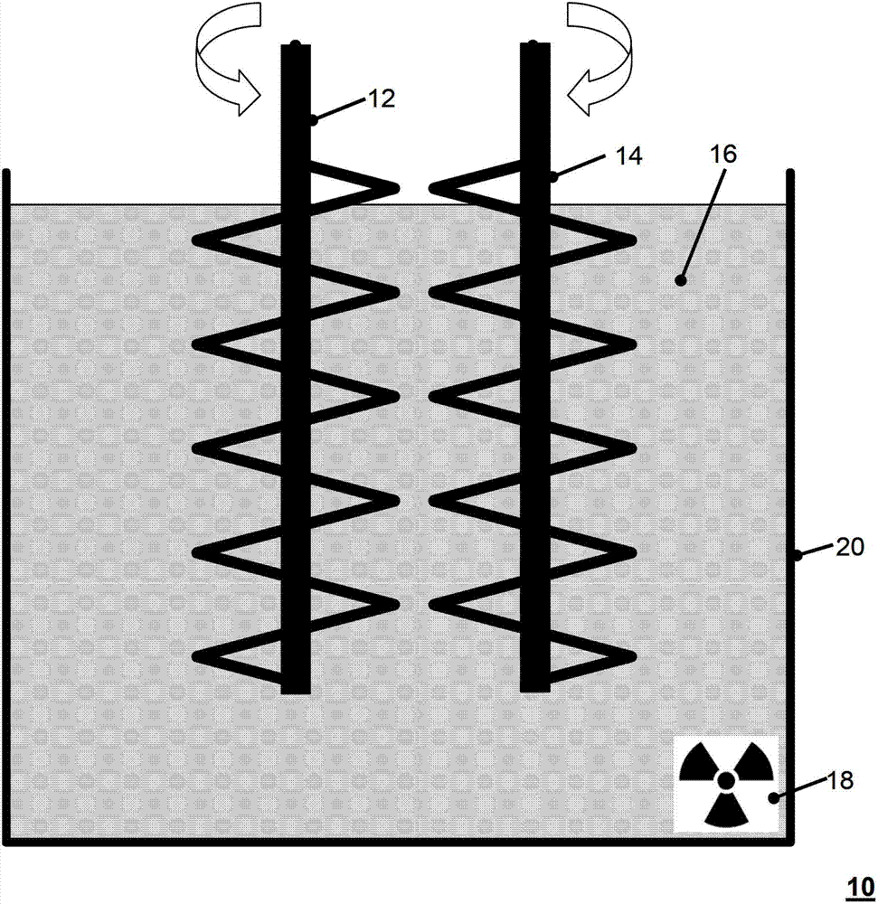
[0034] figure 1 Illustration 10 shows two counter-driven stirrers 12 , 14 in a stirrer container 20 . The stirring vessel is filled with a cement-water mixture to be stirred, which mixture is radioactive, as indicated by reference numeral 18 . Radioactive loading is achieved by mixing radioactive waste, which is safely stored in cement that sets later. The mixers 12 , 14 which come into contact with the cement-water mixture 16 are preferably cleaned after the respective mixing or stirring process. Ideally, however, this cleaning cycle is delayed as long as possible, ie not after every mixing process.

[0035] By coating the mixer with PEEK according to the invention, adhesion of cement or similar materials to be mixed on the mixing tools 12 , 14 is advantageously reduced, so that maintenance intervals are extended. The total amount of cement residues adhering to the mixer which are to be removed as radioactive waste produced during the individual cleaning cycles is thus adv...


PUM

PropertyMeasurementUnit
Layer thicknessaaaaaaaaaa

Abstract

The invention relates to a stirring device (12, 14) used for mixing abrasive material (16). The stirring device (12) has a surface whose partial portion is coated with a protective layer made of polyether ether ketone. Thickness of the protective layer ranges between 500-750 micrometers, where the protective layer is manufactured via electrostatic powder coating and burning processes. The tool is made of stainless steel and designed as two individual stirring tools. The tools are arranged nearby to each other and moved in opposite directions. A driving apparatus rotates the tools. A nuclear safety covering is arranged in a stirred vessel (10).

Description

technical field [0001] The invention relates to a stirrer for mixing grinding materials. The invention also relates to a stirring device and the use of the stirrer or stirring device. Background technique [0002] It is generally known that in nuclear installations, for example nuclear power plants, depending on the operating conditions, in addition to highly radioactive burnt components there are also less radioactive waste materials which likewise need to be removed. This waste may be waste generated during maintenance and renovation work or other material which was previously exposed to intense radiation during its operating time, or which itself contains radioactive materials. Examples here are evaporative concentrates, corrosive sediments or other sludges that are to be removed from the basin within the scope of maintenance. Depending on the reactor size, several 10m 3 size of such waste. To safely store such radioactive waste, it is usually mixed in a cement-water ...

Claims


Application Information

Patent Timeline
IPC IPC(8): B01F7/16B01F7/24B28C5/00B01F23/00
CPCG21C19/32G21F9/008G21F9/165G21F9/304B28C5/0806B28C5/16Y02E30/30B01F27/0531B01F27/922
Inventor 海宁·费尔曼
Owner WESTINGHOUSE ELECTRIC GERMANY
Why Eureka
Try Eureka