
Sampling system

A technology of sampling system and sampling tank, which is applied in the field of sampling system and can solve problems such as complex structure design

Active Publication Date: 2012-05-09
约尔格·维塞尔
View PDF5 Cites 0 Cited by
  • Summary
  • Abstract
  • Description
  • Claims
  • Application Information

AI Technical Summary

Problems solved by technology

However, especially for contamination-free sampling, this construction is very complex in terms of structural design, because an additional connection must be provided, and a row surrounding the sampling system must also be provided from the accessory connection to the sampling chamber. gas line

Method used


Image

  • Sampling system
  • Sampling system
  • Sampling system

Examples


Embodiment Construction

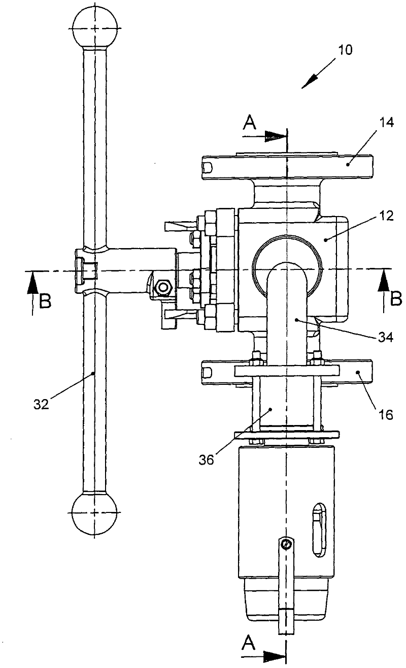
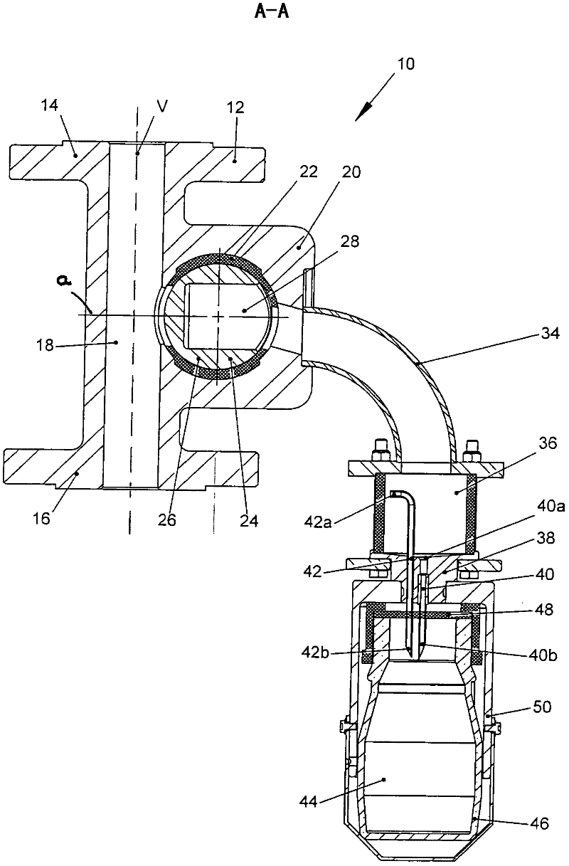
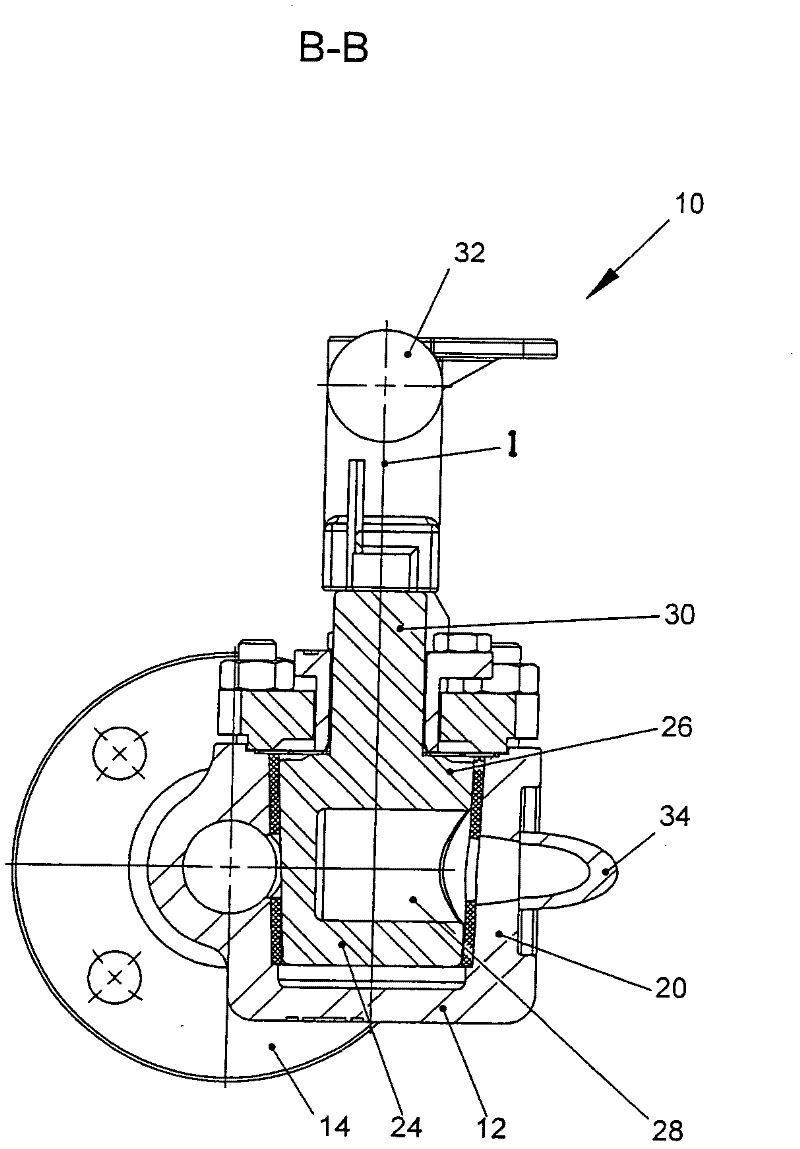
[0022] Figure 1 to Figure 3 Different views of the sampling system 10 are shown, wherein not all reference numbers are shown in all figures in order to simplify the illustration.

[0023] The sampling system 10 has a housing 12, which is substantially cylindrical, with a first connecting piece 14 and a second connecting piece 16, which are connected by a substantially cylindrical, connecting piece. The connecting cavities 18 of the axis v are connected. The first connection piece 14 and the second connection piece 16 can be respectively connected to a fluid flow conduit, so that the housing 12 becomes a part of the fluid flow conduit. The sampling system 10 is used in particular for sampling in lines through which liquids flow.

[0024] A connecting chamber 22 with a longitudinal axis a extends inside the housing 12 transversely to the connection axis v and connects the communicating chamber 18 with the third connecting part 20 . In particular, the connecting chamber 22 ha...


PUM


Abstract

The invention relates to a sampling system (10) which has a first connecting piece (14) for connecting to a pipe traversed by fluid and a third connecting piece (20), and having a cock (24) which has a basic body (26) with a longitudinal axis (1), about which the cock (24) can be pivoted between a first end position and a second end position, and with a sampling recess (28), wherein in the first end position, the sampling recess (28) can be connected via the first connecting piece (14) to the pipe traversed by media, and in the second end position, the sampling recess (28) can be connected to the third connecting piece (20), wherein the third connecting piece (20) is connected to a first end (40a) of an extraction needle (40) which can be pierced with a second end (40b) through a membrane (48) of a sampling volume (44), wherein in the second end position, the sampling recess (28); is connected via the third connecting piece (20) to a first end (42a) of a ventilation needle (42).

Description

technical field [0001] The invention relates to a sampling system according to the preamble of claim 1 . Background technique [0002] Sampling systems are known which have a first connecting piece for connection to a fluid through-flow line and a third connecting piece via which a sample can be taken, said sampling system also having a stopcock which has a base body with a longitudinal axis and a sampling slot and is pivotable about the longitudinal axis between a first end position and a second end position, wherein in the first end position the sampling slot can pass through the second end position A connecting piece is connected to the fluid flow line, while in a second end position the sampling trough can be connected to the third connecting piece. For sampling, the first end of a discharge needle is connected to the third connection piece, said discharge needle being able to pierce the membrane of the sampling chamber with its second end. With this sampling system, i...

Claims


Application Information

Patent Timeline
Patent Type & Authority Applications(China)
IPC IPC(8): G01N1/20
CPCG01N2001/1037G01N1/2035G01N2001/2071G01N2001/2057
Inventor 约尔格·维塞尔
Owner 约尔格·维塞尔
Learn More