A Takeover Combination Structure
A combined structure and casing technology, applied in the direction of pipe/pipe joint/fitting, sleeve/socket connection, petroleum industry, etc., can solve problems such as easy cracking, achieve the effect of reducing coking, reducing residence time, and tight connection
- Summary
- Abstract
- Description
- Claims
- Application Information
AI Technical Summary
Problems solved by technology
Method used
Image
Examples
Embodiment 1
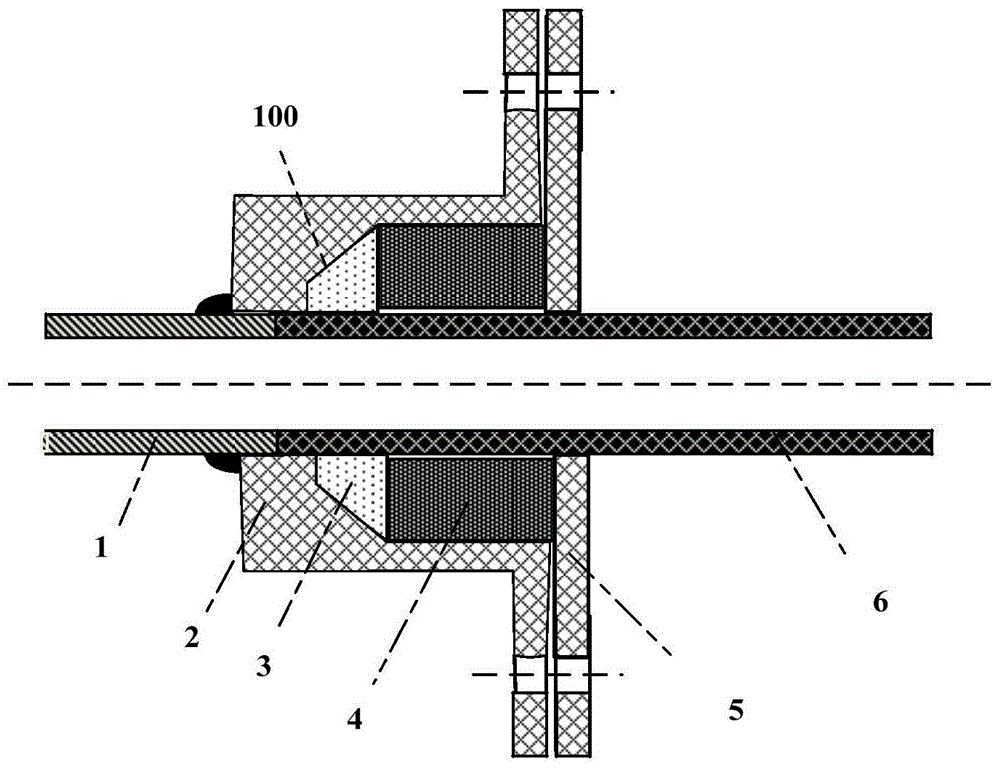
[0036] This embodiment is used to illustrate in the combined structure of ceramic tube and metal pipe joint on the simulated cracking furnace in the laboratory, cracking performance and process parameters of a kind of ceramic cracking furnace tube, the results are as shown in table 2, and the structure is as follows figure 1 shown.
[0037] Put the zirconia cracking furnace tube with the size of Φ14×2×900mm into the laboratory-scale hydrocarbon cracking furnace, and the metal joint between the ceramic cracking furnace tube and the inlet figure 1 Connect as shown. The specific structure is as follows:
[0038] The combined structure of the metal pipe 1 and the ceramic pipe 6 includes the metal pipe 1, the ceramic pipe 6 and the bushing assembly, and is characterized in that:
[0039] The casing assembly includes a sleeve 2, a ceramic fiber gasket 3, a gasket 4 and a sleeve fastening fitting 5;
[0040] One end of the metal pipe 1 is inserted into the sleeve 2;
[0041] One ...
Embodiment 2
[0052] This embodiment is used to illustrate the cracking performance and process parameters of another ceramic cracking furnace tube in the combined structure of ceramic tube and metal pipe joint on the simulated cracking furnace in the laboratory. The results are shown in Table 2.
[0053] Put an alumina cracking furnace tube with a size of Φ14×2×450mm into a laboratory-scale hydrocarbon cracking furnace. The cracking furnace tube is a double-pass straight tube with a total length of 900mm. The ceramic cracking furnace tube and the inlet The metal joints are taken figure 1 Connect as shown. The specific structure is the same as that of Embodiment 1, except that the ceramic tube 6 is a two-way straight tube made of alumina material.
[0054] Use a piston pump to input deionized water into the vaporizer at a certain flow rate, heat the cracking furnace to the cracking temperature, and heat the vaporizer to 600°C at the same time. When the temperature of the cracking furnace...
Embodiment 3
[0057] This embodiment is used to illustrate the cracking performance and operation of the ceramic cracking furnace tube in the combined structure of the ceramic tube and the metal pipe joint on the industrial cracking furnace. The results are shown in Table 2.
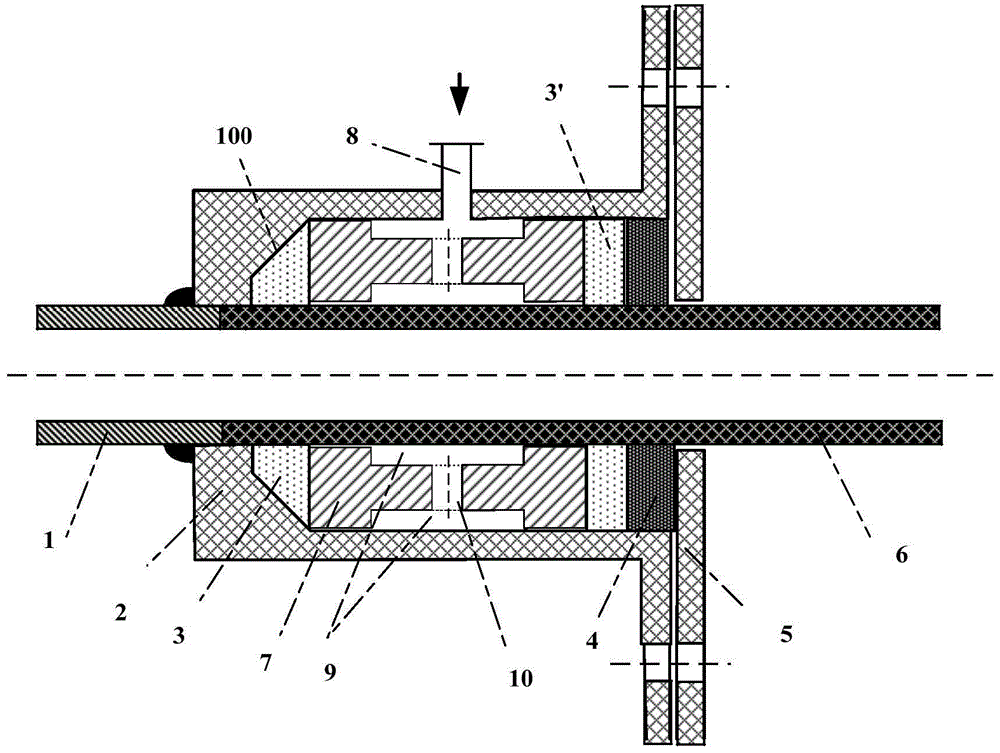
[0058] A straight silicon carbide tube with a length of 4m and an inner diameter of 28mm is used as the radiant section of a 20,000-ton ethylene / year cracking furnace, and the metal joint of the ceramic cracking furnace tube and the inlet is taken figure 2 (General laboratory scale pressure is small, figure 1 The connection method can meet the requirements, figure 2 Due to the presence of protective gas, the connection method can more effectively prevent gas leakage, so figure 1 with figure 2 is set for the raw material scale) to connect in the manner shown. The specific structure is as follows:
[0059] A joint combination structure of ceramic tube 6 and metal tube 1 is usually used in industrial cracking fu...
PUM
 Abstract
Description
Claims
Application Information
 - Generate Ideas
- Intellectual Property
- Life Sciences
- Materials
- Tech Scout
- Unparalleled Data Quality
- Higher Quality Content
- 60% Fewer Hallucinations
Browse by: Latest US Patents, China's latest patents, Technical Efficacy Thesaurus, Application Domain, Technology Topic, Popular Technical Reports.
© 2025 PatSnap. All rights reserved.Legal|Privacy policy|Modern Slavery Act Transparency Statement|Sitemap|About US| Contact US: help@patsnap.com


