Method for making liquid ink gun, liquid ink gun and printing equipment
A technology of a liquid inkjet head and a manufacturing method, which is applied in the field of liquid inkjet head and printing equipment, and the manufacture of liquid inkjet head, can solve problems such as poor injection accuracy, and achieve the effect of improving printing speed
- Summary
- Abstract
- Description
- Claims
- Application Information
AI Technical Summary
Problems solved by technology
Method used
Image
Examples
Embodiment 1
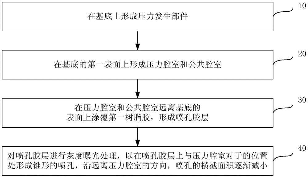
[0045] figure 1 It is a flow chart of the manufacturing method of the liquid inkjet head provided by Embodiment 1 of the present invention. Such as figure 1 As shown, the manufacturing method of the liquid inkjet head may include:
[0046] Step 10, forming a pressure generating component on the substrate.
[0047] Step 20, forming a pressure chamber and a common chamber on the first surface of the substrate.
[0048] Step 30, coating the first resin glue on the surfaces of the pressure chamber and the common chamber away from the substrate to form a spray hole glue layer.
[0049] Step 40: Carry out gray-scale exposure treatment on the spray hole glue layer to form a tapered spray hole at the position on the spray hole glue layer opposite to the pressure chamber. Along the direction away from the pressure chamber, the cross-sectional area of the spray hole is slowing shrieking.
[0050] The aforementioned substrate may be a silicon substrate or a glass substrate, and a ...
Embodiment 2
[0097] This embodiment provides another method for forming a pressure generating component on the basis of the above embodiments, which may specifically include:
[0098] The vibrating plate 4 is formed by depositing on the first surface of the substrate 1 .
[0099] Specifically, it can be formed by low-pressure chemical vapor deposition or plasma-enhanced chemical vapor deposition, and the material of the vibrating plate 4 can be SiO 2 、Si 3 N 4 or SiO 2 -Si 3 N 4 stacks. This step can refer to Figure 10 , Figure 10 It is a schematic structural diagram of forming a vibrating plate on the surface of a substrate in the method for manufacturing a liquid inkjet head provided in Embodiment 2 of the present invention.
[0100] The piezoelectric element 3 is formed on the surface of the vibrating plate 4 away from the base 1 .
[0101] Specifically, the lower electrode layer can be formed by sputtering, the piezoelectric layer can be formed by sol-gel method, and the upp...
Embodiment 3
[0104] This embodiment provides yet another method for forming a pressure generating component on the basis of the above embodiments, which specifically includes:
[0105] A thin film resistance layer 19 is deposited on the first surface of the substrate 1 .
[0106] Specifically, the thin film resistance layer 19 can be deposited on the substrate 1 , and the material of the thin film resistance layer 19 can be one of tantalum aluminum alloy, nickel cadmium alloy, tungsten silicon nitride and titanium nitride. Can refer to Figure 13 , Figure 13 It is a schematic structural diagram of forming a thin-film resistance layer on a substrate in the method for manufacturing a liquid inkjet head provided in Embodiment 3 of the present invention.
[0107] For the forming method of other components in the liquid inkjet head, reference may be made to the technical solutions provided in the above embodiments, and details will not be repeated here. The formed liquid inkjet head structu...
PUM
 Abstract
Description
Claims
Application Information
 - R&D
- Intellectual Property
- Life Sciences
- Materials
- Tech Scout
- Unparalleled Data Quality
- Higher Quality Content
- 60% Fewer Hallucinations
Browse by: Latest US Patents, China's latest patents, Technical Efficacy Thesaurus, Application Domain, Technology Topic, Popular Technical Reports.
© 2025 PatSnap. All rights reserved.Legal|Privacy policy|Modern Slavery Act Transparency Statement|Sitemap|About US| Contact US: help@patsnap.com


