
Austenite furnace tube welding method

A welding method and austenitic technology, applied in welding equipment, welding accessories, tubular objects, etc., can solve the problems of no welding technology for stainless steel self-shielding flux-cored welding wire, lagging welding operation standards, insufficient knowledge of flux-cored welding wire, etc., to achieve Reduce the amount of dissolved carbon, avoid intergranular corrosion, and reduce the effect of residual stress

Active Publication Date: 2015-03-25
CHINA NAT CHEM ENG NO 16 CONSTR +1
View PDF4 Cites 3 Cited by
  • Summary
  • Abstract
  • Description
  • Claims
  • Application Information

AI Technical Summary

Problems solved by technology

[0004] At present, the use of stainless steel self-shielding flux-cored wire in our country is only popularized and applied in shipbuilding and boiler industries due to insufficient understanding of flux-cored wire and the serious lag in some welding operation standards. Other industries basically still use electrode arc welding as the mainstay. Master, low production efficiency
Therefore, at present, there is no mature welding technology for the use of stainless steel self-shielding flux-cored wire in the furnace tube in China.

Method used


Image

  • Austenite furnace tube welding method

Examples


Embodiment Construction

[0017] The present invention will be further described in detail below in conjunction with the accompanying drawings, so that those skilled in the art can implement it with reference to the description.

[0018] The invention provides a method for welding an austenitic furnace tube, comprising the following steps:

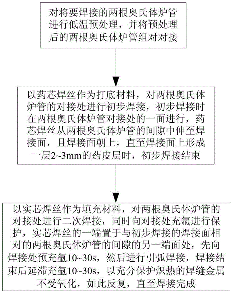
[0019] Step 1. As the temperature drops, the carbon dissolving ability of austenite decreases, and one of the main measures to avoid intergranular corrosion, reduce residual stress during welding, and prevent hot cracks is to reduce the weld and base metal. Carbon content, perform low-temperature pretreatment on the two austenitic furnace tubes to be welded, place the two furnace tubes in an ice-water mixed bath for 5 to 8 hours, and put the pretreated two austenitic furnace tubes Placed on a horizontal workbench for pairing and docking;

[0020] Step 2. Use flux-cored wire as the base material, and conduct preliminary welding on the butt joint of two austenitic f...


PUM


Abstract

The invention relates to the field of furnace tube welding, in particular to an austenite furnace tube welding method. The method comprises the steps that two preprocessed austenite furnace tubes are assembled and connected in an abutting mode; a flux-cored wire is used as backing welding materials, preliminary welding is carried out on one face of the position where the two austenite furnace tubes are connected in the abutting mode, the flux-cored wire extends from a gap between the two austenite furnace tubes to the welding face, the welding face faces upwards, and preliminary welding is ended when a coating layer is formed on the welding face; a flux-cored wire is used as filling materials, secondary welding is carried out on the position where the two austenite furnace tubes are connected in the abutting mode, meanwhile, the abutting connection position is filled with argon for protection, one end of the flux-cored wire is placed on the other end face, opposite to the welding face where the preliminary welding is carried out, of the gap between the two austenite furnace tubes, the flux-cored wire is molten constantly until welding is completed. According to the austenite furnace tube welding method, inconvenience brought when furnace tube bottoming welding tubes are filled with argon for protection is omitted, argon is saved, working efficiency is improved, meanwhile, crystal corrosion is avoided, residual stress in the welding process is reduced, and hot cracks are prevented from being generated.

Description

technical field [0001] The invention relates to the field of furnace tube welding, in particular to an austenite furnace tube welding method. Background technique [0002] For austenitic stainless steel pipes, the commonly used welding method is tungsten inert gas shielded welding (TIG), that is, manual tungsten argon arc welding with solid welding wire as the backing welding method, and the pipe is filled with argon to prevent oxidation of the root of the weld , to ensure the internal quality of the weld. However, in the welding process of stainless steel furnace tubes, there are many factors that plague the construction, such as the complex welding process of furnace tubes, and sometimes the protection of argon filling is easy to fail; the pipe connection is long, the amount of argon filling is large, and the argon filling welding port from the groove cannot be sealed The distribution of welding joints is scattered, the utilization rate of argon gas is low, and the weldin...

Claims


Application Information

Patent Timeline
Patent Type & Authority Applications(China)
IPC IPC(8): B23K9/16B23K9/32
CPCB23K9/16B23K9/235B23K2101/06
Inventor 李仁国张波查翔李云松
Owner CHINA NAT CHEM ENG NO 16 CONSTR
Learn More