
Punching hole distance adjustable compound die for double-long-hole workpiece

An adjustable and composite mold technology, applied in the field of composite molds, can solve the problems of lower production efficiency, less than guaranteed accuracy, waste of time and labor, etc., and achieve the effects of improving precision and quality, prolonging service life, and improving production efficiency

Inactive Publication Date: 2015-03-25
WUZHONG DISTRICT GUANGFU JINYI HARDWARE FITTINGS FACTORY
View PDF5 Cites 5 Cited by
  • Summary
  • Abstract
  • Description
  • Claims
  • Application Information

AI Technical Summary

Problems solved by technology

[0002] Double long-hole workpieces are commonly used parts in belt conveyors. Different double-long-hole workpieces have different hole distances. During the production process, they are processed in two punching processes. This production method is not only costly, but also low in efficiency. It is time-consuming and labor-intensive, and the error of the center distance between the two holes is also very large, so it is difficult to guarantee the processing quality. In addition, the punches commonly used in the industry are constantly rubbing against the steel parts during use, resulting in wear and tear, resulting in the processing of holes. The size has been changing, the accuracy is not guaranteed, and the situation of wear and tear failure has also appeared frequently.
If you need to process holes with high precision requirements, you need to replace the punch frequently, which wastes time and labor and reduces production efficiency.

Method used


Image

  • Punching hole distance adjustable compound die for double-long-hole workpiece
  • Punching hole distance adjustable compound die for double-long-hole workpiece

Examples


Embodiment Construction

[0012] The present invention will be further described in detail below in conjunction with the accompanying drawings and specific embodiments.

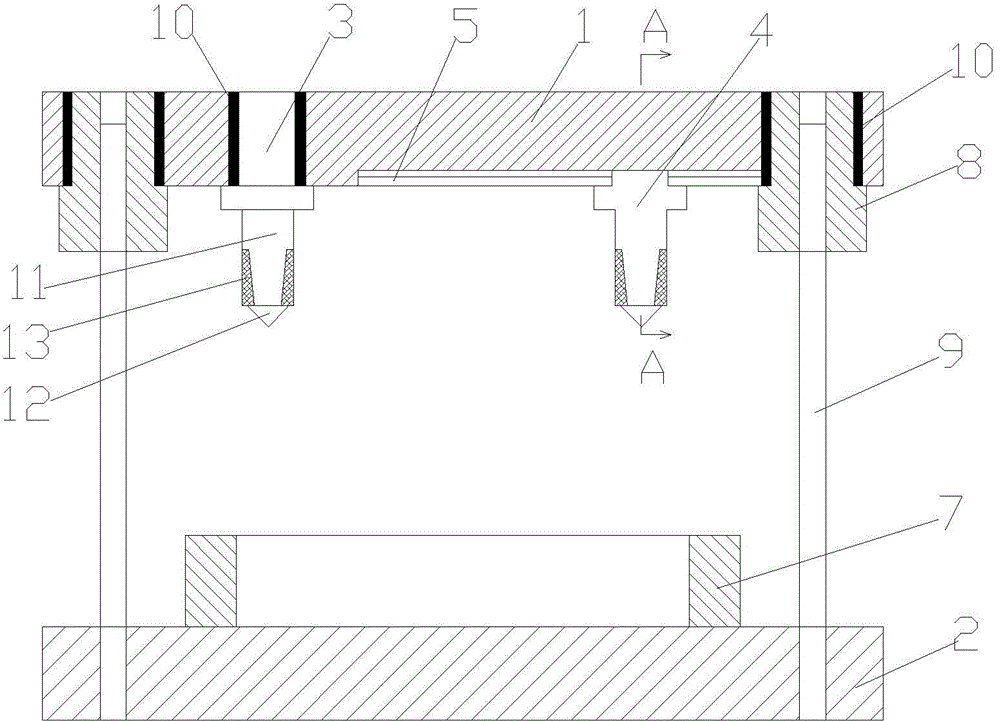
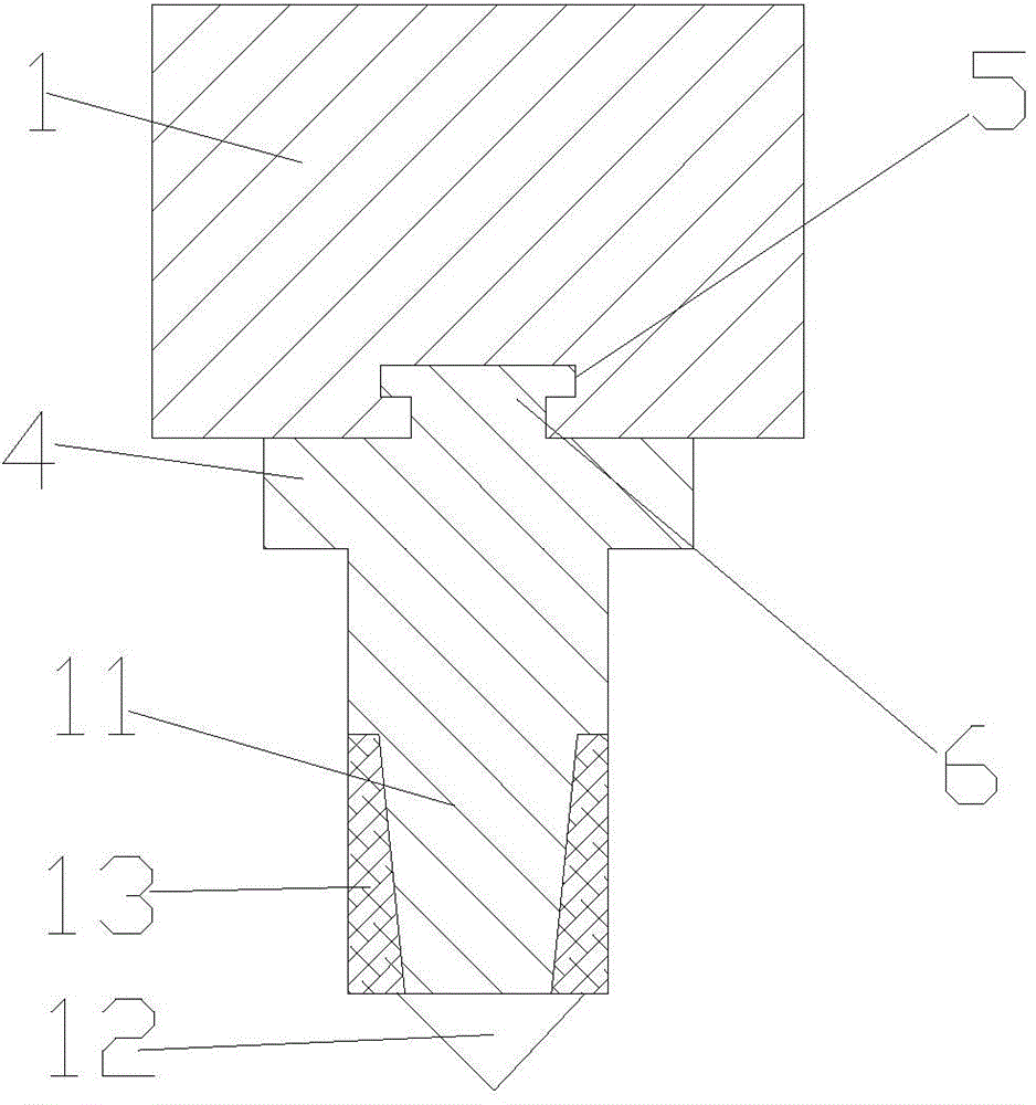
[0013] attached figure 1 , 2 It is a compound die with adjustable punching distance for a double long-hole workpiece according to the present invention, which includes an upper die base 1 and a lower die base 2 installed oppositely, and a fixed punch 3 is arranged at an interval at the bottom of the upper die base 1 and a movable punch 4; the upper mold base 1 is provided with a dovetail groove 5; the upper part of the movable punch 4 is provided with a dovetail block 6; the dovetail block 6 is arranged in the dovetail groove 5; the lower Die base 2 is provided with die 7, and described punch comprises guiding part 11 and working part 12; Described guiding part 11 is arranged on the below of working part 12; Described guiding part 11 is a cone, and described working part 12 An alloy ring 13 is provided on the outer periphery of the ...


PUM


Abstract

The invention relates to a punching hole distance adjustable compound die for a double-long-hole workpiece. The punching hole distance adjustable compound die for the double-long-hole workpiece comprises an upper mold holder and a lower mold holder opposite to the upper mold holder; the bottom of the upper mold holder is provided with a fixed punch and a movable punch in a spaced mode; the upper mold holder is provided with a dovetail groove; a dovetail block is arranged above the movable punch and located in the dovetail groove. Each punch comprises a guide portion and a working portion, wherein the guide portion is arranged below the working portion and is a conical part; an alloy ring is arranged on the periphery of the front working end face of the working portion; the alloy ring is made of low-nickel-chromium-molybdenum alloy. Through design of the fixed punch and the movable punch, double holes are be formed in a punched mode at a time by adjusting the distance between the punches according to the requirement for hole distance, so that the production efficiency is improved, the center distance between the two holes is ensured, and the machining quality of the workpiece is ensured. Through the structural design of the punches, the punching service life of the punches is prolonged, and the precision and quality of punched holes are improved.

Description

technical field [0001] The invention relates to a composite mold, in particular to a composite mold with adjustable punching distance for workpieces with double long holes. Background technique [0002] Double long-hole workpieces are commonly used parts in belt conveyors. Different double-long-hole workpieces have different hole distances. During the production process, they are processed in two punching processes. This production method is not only costly, but also low in efficiency. It is time-consuming and labor-intensive, and the error of the center distance between the two holes is also very large, so it is difficult to guarantee the processing quality. In addition, the punches commonly used in the industry are constantly rubbing against the steel parts during use, resulting in wear and tear, resulting in the processed holes The size of the machine has been changing, the accuracy is not guaranteed, and the situation of wear and tear failure has appeared frequently. If...

Claims


Application Information

Patent Timeline
IPC IPC(8): B21D28/34
CPCB21D28/34
Inventor 黄建芳
Owner WUZHONG DISTRICT GUANGFU JINYI HARDWARE FITTINGS FACTORY
Learn More