High-speed metal pipe wall punching device and method

A punching device and high-speed technology, which is applied in the field of high-speed punching devices for metal pipe walls, can solve problems affecting the shape and quality of the pipe wall around the hole, and achieve good application prospects, uniform and reliable force, and low-cost processing Effect

Inactive Publication Date: 2015-03-25
HARBIN INST OF TECH
View PDF6 Cites 2 Cited by
  • Summary
  • Abstract
  • Description
  • Claims
  • Application Information

AI Technical Summary

Problems solved by technology

[0003] The purpose of the present invention is to provide a high-speed punching device and method for metal pipe walls, so as to solve the problem that the shape and quality of the pipe wall around the hole are affected due to the gap between the punch and the die during the existing mechanical punching.

Method used


Image

  • High-speed metal pipe wall punching device and method
  • High-speed metal pipe wall punching device and method
  • High-speed metal pipe wall punching device and method

Examples


specific Embodiment approach 1

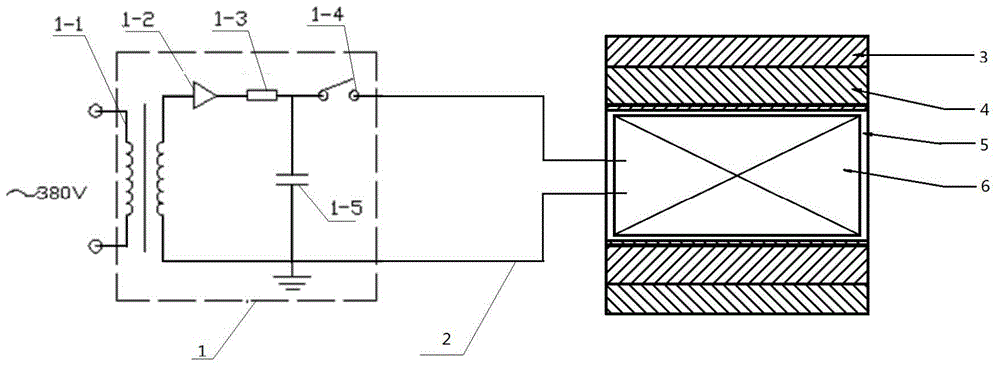
[0013] Specific implementation mode one: combine figure 1 Describe this embodiment, the device described in this embodiment includes a pulse power supply 1, a connecting wire 2, an outer mold 3, two half molds 4, a pipe fitting 5 to be punched and a coil 6, and the pulse power supply 1 includes a high-voltage transformer 1-1, a rectifier 1-2, current-limiting resistor 1-3, high-voltage switch 1-4 and high-voltage pulse capacitor 1-5, the two power terminals of the primary side of the high-voltage transformer 1-1 are connected to the external power supply, and the secondary side of the high-voltage transformer 1-1 One end is connected to the anode of the rectifier 1-2, the cathode of the rectifier 1-2 is connected to one end of the current limiting resistor 1-3, the other end of the current limiting resistor 1-3 is connected to the positive pole of the high voltage pulse capacitor 1-5 and the high voltage switch The positive poles of 1-4 are connected, the negative pole of the ...

specific Embodiment approach 2

[0014] Specific implementation mode two: combination figure 1 Describe this embodiment, each half-mold 4 of this embodiment is manufactured by machining of high-strength alloy, this kind of material has high strength and high hardness, and the cutting edge of the mold processed with it is sharp and has high wear resistance. Other implementation manners are the same as the specific implementation manner 1.

specific Embodiment approach 3

[0015] Specific implementation mode three: combination figure 1 To illustrate this embodiment, the coil 6 of this embodiment is composed of rectangular cross-section, high-conductivity red copper turns wound on an insulating cylindrical skeleton and covered with a high-voltage insulating material outside the turns. This coil has a compact structure and low self-inductance Small, small radial gap with the pipe to be processed, which is conducive to improving the conversion efficiency of magnetic field energy to mechanical energy. Other implementation manners are the same as the specific implementation manner 1.


PUM

PropertyMeasurementUnit
Diameteraaaaaaaaaa
Capacitanceaaaaaaaaaa

Abstract

The invention discloses a high-speed metal pipe wall punching device and method and belongs to the field of machine manufacturing. The device and method solve the problem that in the prior art, during mechanical punching, the shape and quality of a peripheral pipe wall are affected due to the fact that a gap exists between a male die and a female die. According to the scheme of the high-speed metal pipe wall punching device, one output end of a pulse power supply is connected with one terminal of a coil, the other terminal of the coil is connected with the other output end of the pulse power supply, two half dies are embedded in a jacket die, a pipe to be punched is arranged in the two half dies, and the coil is arranged in the pipe to be punched. According to the scheme of the high-speed metal pipe wall punching method, the coil, the pipe to be punched, the half dies and the jacket die are assembled, outer grid voltage is connected with a high voltage switch after being boosted through a high voltage transformer, a pulse load enables the pipe to be punched to be subjected to the high-speed deformation process including expansion, shearing and breakage in sequence along the edge of a hole formed by the two half dies through hindrance of the two half dies, and then punching is achieved. The device and method are used for punching metal pipes.

Description

technical field [0001] The invention relates to a high-speed punching device and method for a metal pipe wall, belonging to the field of mechanical manufacturing. Background technique [0002] The punching method of metal pipe fittings is difficult to carry out without affecting the shape of the pipe fittings. The usual mechanical punching method will affect the shape and quality of the pipe wall around the hole due to the gap between the punch and the die during punching. Such as the formation of warping and burrs. Traditional mechanical punching cannot avoid the design problems of the punch and die edges, so the traditional metal pipe wall punching method cannot efficiently produce high-quality metal holes. Contents of the invention [0003] The purpose of the present invention is to provide a high-speed punching device and method for metal pipe wall to solve the problem that the shape and quality of the pipe wall around the hole are affected due to the gap between the ...

Claims


Application Information

Patent Timeline
IPC IPC(8): B21D26/14
Inventor 于海平李送斌于世豪
Owner HARBIN INST OF TECH
Why Eureka
Try Eureka