
Load charger applied to friction test machine

A friction testing machine and loading device technology, applied in the field of machinery, can solve the problems of inability to realize pulsating impact load, uncontrollable spring elastic force, and inability to load pulsating impact, so as to reduce frictional noise, reduce frictional heat generation, and reduce Effect of small frictional energy loss

Active Publication Date: 2008-12-24
HENAN UNIV OF SCI & TECH
View PDF0 Cites 9 Cited by
  • Summary
  • Abstract
  • Description
  • Claims
  • Application Information

AI Technical Summary

Problems solved by technology

In the existing friction and wear test equipment, there are two loading methods: one is completely constant load loading, and pulsating impact cannot be loaded. In the test, only the influence of pantograph lifting force on the slide plate and wire can be simulated, and various impacts cannot be investigated. The impact of load; another loading method is to add a spring to the pin sample fixture on the basis of constant load loading to reduce the impact of the contact vibration on the pin sample during the test and simulate the flexible contact of the wire, but The elastic force generated by the spring is entirely derived from passively bearing the impact force from the pin sample, and the elastic force generated by the spring is uncontrollable, and it is impossible to apply pulsating impact loads with different rules (waveforms)

Method used


Image

  • Load charger applied to friction test machine

Examples


Embodiment Construction

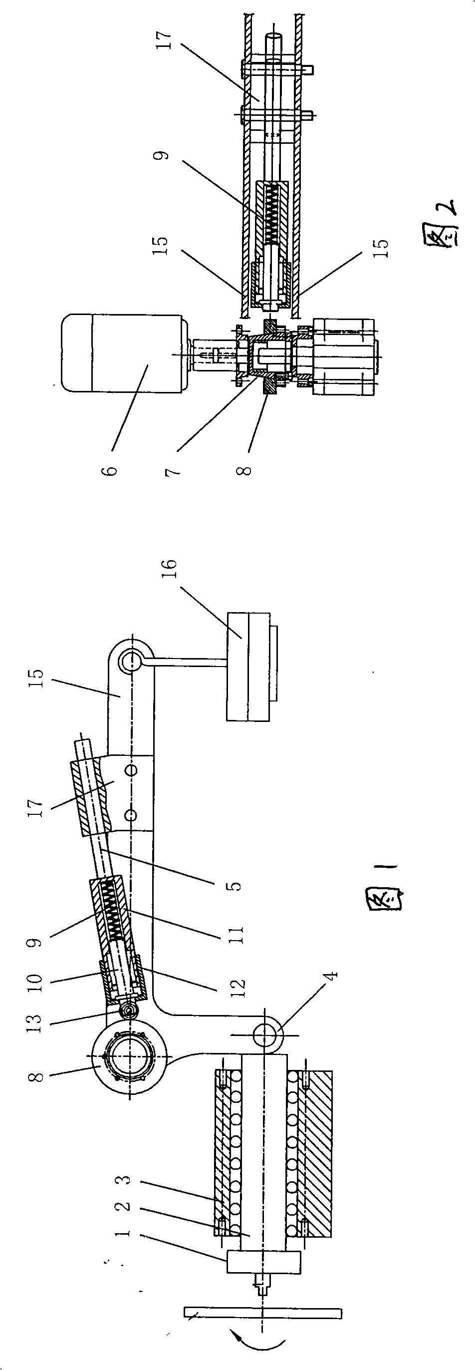
[0016] As shown in Figure 1 and Figure 2, in this load pulsating loading device, the pin sample fixture 1 is fixed at one end of the dowel bar 2, and the rod body of the dowel bar 2 is assembled on the loading device through the bearing 3 in a manner of moving linearly in the axial direction. On the main body, a set of constant load loading device is arranged on the body of the loading device at the other end of the dowel bar 2. The load output head 4 of the constant load loading device loads a constant pressure on the end face of the end. A set of flexible pulsation generating mechanism is added, the flexible pulsation output of the flexible pulsation generating mechanism is superimposed on the load of the constant load loading device, and then applied to the corresponding end surface of the dowel bar through the load output head of the constant load loading device. The flexible pulsation generating mechanism is composed of a reciprocating motion generator and a flexible recip...


PUM


Abstract

The invention relates to a load pulse loading device. The pin sample clamp of the device is fixed at one end of a dowel steel; the rod body of the dowel steel is assembled on the body of the loading device in a way of linear movement in the axis line direction; the body of the loading device which is arranged at the other end of the dowel steel is provided with a constant-load loading device; the load output head of the constant-load loading device is arranged on the end surface of the end; a flexible pulse generation mechanism is added on the constant-load loading device; the flexible pulse output of the flexible pulse generation mechanism is superposed with the load of the constant-load loading device and is subsequently exerted on the corresponding end surface of the dowel steel by the load output head of the constant-load loading device. The load pulse loading device of the invention follows the traditional mechanism-typed impact loading characteristics such as simple and easy realization, and easy control, etc., and reduces the noise generated by the impact loading by using the flexible loading characteristic of the spring.

Description

technical field [0001] The invention relates to a load loading device applied to a friction testing machine, which belongs to the technical field of machinery. Background technique [0002] Pulsating loading or pulsating impact loading is a commonly used loading form in experiments and practical engineering, and it is an important means to study the performance of materials under impact conditions. The ways to realize pulsating loading include electromagnetic loading method, hydraulic method and traditional mechanical method. Electromagnetic loading method The pulsating load excitation signal is greatly disturbed by the outside world, the loading force is not easy to control, and the loading force is small; the pulsating loading is realized by the hydraulic method, the system response is slow and easy to lag, and high-frequency loading cannot be realized; traditional mechanical loading mostly uses polarization Or transmission type, the disadvantage is that the frequency and...

Claims


Application Information

Patent Timeline
IPC IPC(8): G01N3/34G01N3/56
Inventor 张永振李键李鹏上官宝高万振
Owner HENAN UNIV OF SCI & TECH
Learn More