
Implanted type intracranial pressure wireless monitoring device

A monitoring device and intracranial pressure technology, which are used in intracranial pressure measurement, medical science, diagnosis, etc., can solve the problems of limited monitoring range, low monitoring efficiency, and difficult implementation, and achieve large monitoring range, convenient operation and implementation easy effect

Inactive Publication Date: 2015-03-25
CHENGDU UNIV OF INFORMATION TECH
View PDF9 Cites 8 Cited by
  • Summary
  • Abstract
  • Description
  • Claims
  • Application Information

AI Technical Summary

Problems solved by technology

[0006] The purpose of the present invention is that the existing intracranial pressure monitoring technology is usually complicated in operation, difficult in implementation, and high in infection rate. At the same time, the monitoring range is limited, the monitoring efficiency is low, and the effect is poor, which cannot truly, accurately, and effectively reflect the pressure changes in the entire intracranial In view of the problem, a simple and reasonable structural design, convenient operation, easy implementation and no infection, large monitoring range, accurate and effective monitoring of the entire intracranial pressure change for a long time, safe, reliable and efficient use are proposed. Implantable wireless intracranial pressure monitoring device

Method used


Image

  • Implanted type intracranial pressure wireless monitoring device
  • Implanted type intracranial pressure wireless monitoring device
  • Implanted type intracranial pressure wireless monitoring device

Examples


Embodiment Construction

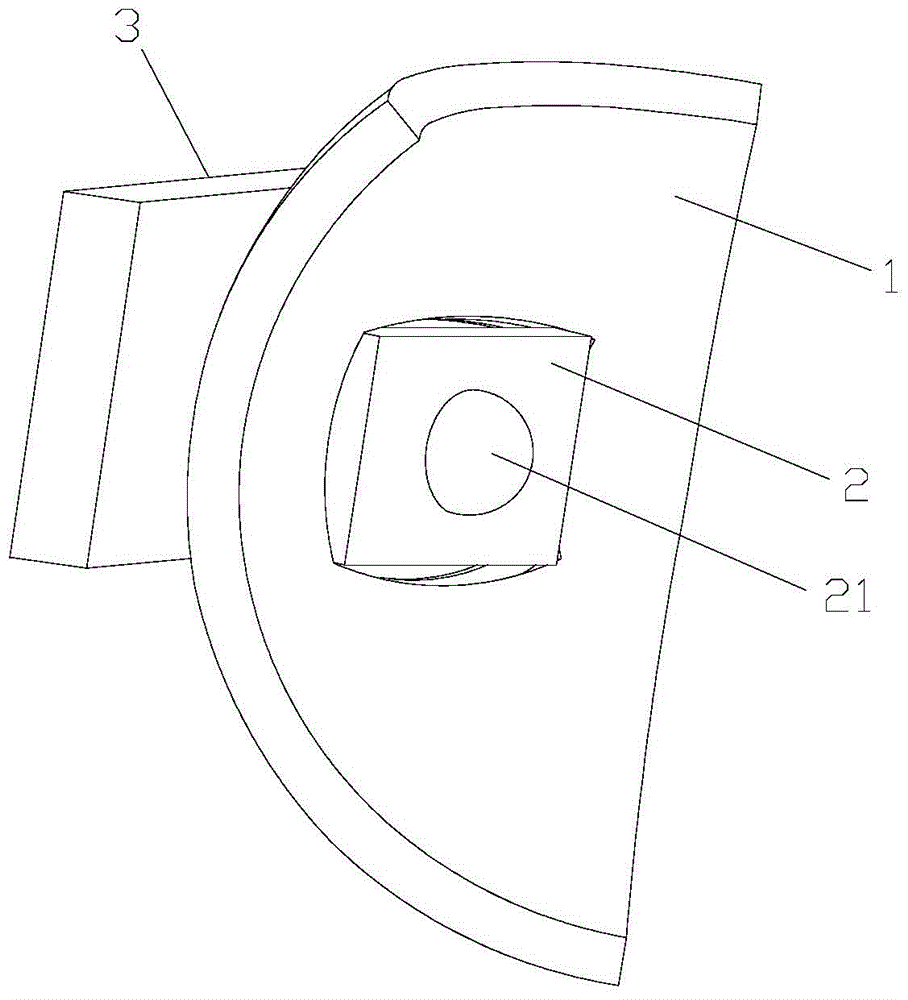
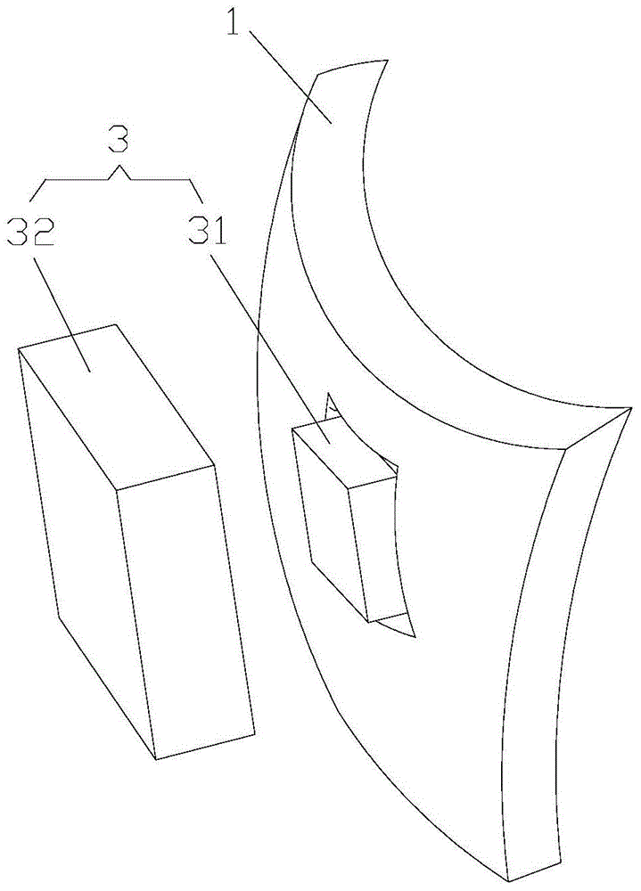
[0021] Such as Figures 1 to 5 As shown, the implantable intracranial pressure wireless monitoring device of the present invention includes an artificial skull 1 , a pressure detection module 2 and a wireless power supply transmission module 3 .

[0022] The artificial skull 1 is used to replace the removed part of the skull after the creation of the brain. The artificial skull 1 is made of zirconia that has the least side effects on the body and is not rejected by the body's immune system. Its overall shape is a curved shell structure and A square through hole 11 is provided in the middle, and a square groove 12 is provided along the edge of the through hole 11 on the side of the artificial skull 1 close to the brain tissue.

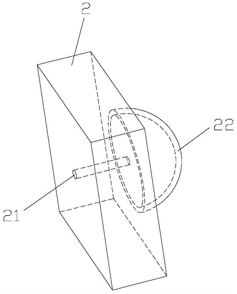
[0023] The pressure detection module 2 is installed on the artificial skull 1, specifically embedded in the groove 12 on the side of the artificial skull 1 close to the brain tissue, wherein the pressure detection module 2 adopts a miniature liquid pres...


PUM


Abstract

The invention relates to an implanted type intracranial pressure wireless monitoring device which comprises an artificial skull, a pressure detecting module and wireless power supply and transmitting modules. The artificial skull is of a cambered-surface shell structure. The wireless power supply and transmitting modules comprise an inner wireless power supply and transmitting module and an outer wireless power supply and transmitting module. The outer wireless power supply and transmitting module and the inner wireless power supply and transmitting module are in wireless communication connection, and are connected with an external power source and an oscilloscope at the same time. The pressure detecting module is powered by the inner wireless power supply and transmitting module. A micro liquid pressure sensor is adopted as the pressure detecting module, and the pressure detecting module is connected with an inner wireless power supply and transmitting module through a wire. A liquid inlet of the micro liquid pressure sensor is covered with a thin film. The overall thin film is of a spherical-surface thin film structure and is filled with a proper amount of normal saline. The implanted type intracranial pressure wireless monitoring device is simple in structure and easy to implement, infection cannot be generated, the monitoring range is large, the whole intracranial pressure changes can be monitored accurately and effectively for a long time, use is safe and reliable, and efficiency is high.

Description

technical field [0001] The invention relates to the technical field of intracranial pressure monitoring, in particular to an implantable wireless monitoring device for intracranial pressure. Background technique [0002] At present, the commonly used monitoring methods of intracranial pressure in clinic are invasive monitoring methods with high precision, but they are easy to cause complications such as infection, bleeding, malfunction and embolism. There are certain risks, such as complex operation, difficult to repeat, and long-term monitoring. Invasive intracranial pressure monitoring was first applied by Guillaume and Janny in 1951. According to different pressure sensing methods, it can be divided into hydraulic sensing monitoring, non-invasive intracranial pressure monitoring Hydraulic pressure sensing monitoring and optical fiber sensing intracranial pressure monitoring. Among them, the probe is placed in the ventricle, epidural, subdural, subarachnoid space, brain p...

Claims


Application Information

Patent Timeline
IPC IPC(8): A61B5/03
CPCA61B5/031
Inventor 李永红余杭郭盼盼李沂玥杨小平
Owner CHENGDU UNIV OF INFORMATION TECH
Learn More