Method for producing polysilicon
A manufacturing method, polysilicon technology, applied in the steam generation method using heat carrier, chemical instruments and methods, sustainable manufacturing/processing, etc., can solve problems such as polymer ignition
- Summary
- Abstract
- Description
- Claims
- Application Information
AI Technical Summary
Problems solved by technology
Method used
Image

Examples
Embodiment 1
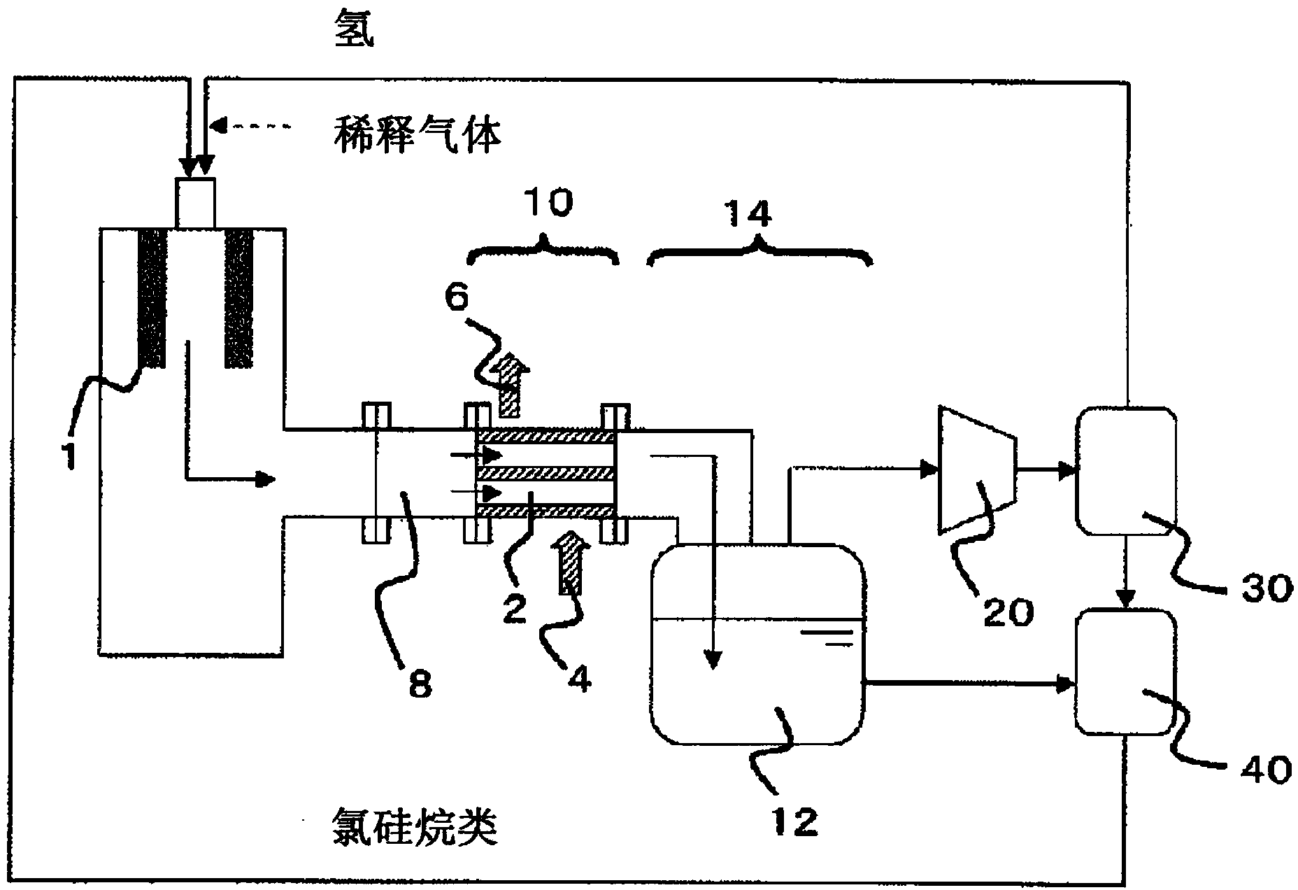
[0108] follow figure 1 The flow chart shows the steps to manufacture polysilicon. The deposition step of depositing polysilicon is performed by the VLD method.
[0109] The temperature of the silicon precipitation part of the cylindrical reaction vessel 1 was raised to 1300° C., and a source gas was supplied to precipitate silicon. Thereafter, the silicon deposited in the cylindrical reaction container was melted and dropped by controlling the heating of the cylindrical reaction container to 1600° C. in the melting step, and recovered. Silicon is produced by repeating the precipitation step and the melting step.
[0110] In the precipitation step, supply hydrogen 2000Nm 3 / h and trichlorosilane as chlorosilane 1200kg / h (about 200Nm 3 / h) mixed gas (about 2200Nm 3 / h) react as raw material gas. The temperature of the exhaust gas discharged through the precipitation step was measured and found to be 1050°C. In addition, the outlet pressure of the boiler type heat recovery...
Embodiment 2
[0118] In the deposition step, the same operation as in Example 1 was carried out except that hydrogen as a raw material gas was increased.
[0119] Specifically, in the precipitation step, supply hydrogen 3000Nm 3 / h and trichlorosilane as chlorosilane 1200kg / h (about 200Nm 3 / h) mixed gas (about 3200Nm 3 / h) react as raw material gas. In addition, the outlet pressure of the boiler type heat recovery device at the time of a precipitation process was adjusted so that it may become 50 kPaG. As a boiler type heat recovery device, the same device as in Example 1 was used.
[0120] The temperature of the exhaust gas discharged through the precipitation step was measured and found to be 1110°C.
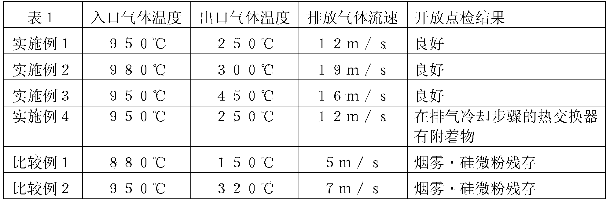
[0121] The exhaust gas temperatures before and after the boiler-type heat recovery device in the precipitation step were 980° C. and 300° C., and the initial pressure difference was about 10 kPa. The overall heat transfer coefficient U is estimated to be 206W m -2 ·K -1 .
[0122] F...
Embodiment 3
[0125] For the exhaust pipe 2 of the boiler-type heat recovery device, use the same inner diameter and number as the exhaust pipe of Example 1, but use an exhaust pipe whose total length is about 1 / 3 of the exhaust pipe of Example 1, and the others are The same operation as in Example 1 was carried out. As a result, the gas temperature at the outlet of the boiler-type heat recovery device was about 450°C. In addition, the flow velocity of the exhaust gas at the outlet of the exhaust pipe in the boiler-type heat recovery device in the precipitation step was 16 m / s.
[0126] The above-mentioned operation was continued for one month, but the pressure difference before and after the boiler-type heat recovery device did not change, and thereafter, in the boiler-type heat recovery device, the gas introduction pipe, and even the exhaust gas from the hydrogen refining treatment device in the exhaust gas cooling step Opening checks are carried out in the processing system, but it is c...
PUM
| Property | Measurement | Unit |
|---|---|---|
| particle diameter | aaaaa | aaaaa |
Abstract
Description
Claims
Application Information
 - R&D
- Intellectual Property
- Life Sciences
- Materials
- Tech Scout
- Unparalleled Data Quality
- Higher Quality Content
- 60% Fewer Hallucinations
Browse by: Latest US Patents, China's latest patents, Technical Efficacy Thesaurus, Application Domain, Technology Topic, Popular Technical Reports.
© 2025 PatSnap. All rights reserved.Legal|Privacy policy|Modern Slavery Act Transparency Statement|Sitemap|About US| Contact US: help@patsnap.com